Dell Latitude XPi Service Manual - Page 62
LCD Inverter Board, LCD Inverter Board Removal
 |
View all Dell Latitude XPi manuals
Add to My Manuals
Save this manual to your list of manuals |
Page 62 highlights
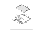
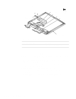
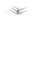
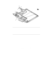
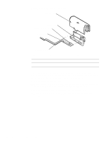
LCD Inverter Board I1 (5 mm) I2 (5 mm) retaining bracket connector CN1 inverter board 5 mm connector CN2 LED board Figure 4-18. LCD Inverter Board Removal display assembly case Part or Assembly Name LCD inverter board Order Name ASSY,BD,INVRTR,TFT,SVGA12.1" To remove the LCD inverter board, follow these steps: 1. Remove the display assembly bezel. 2. Remove screws I1 and I2 securing the display-interface cable retaining bracket, and then remove the bracket. 3. Move the LED board out of the display assembly case far enough to gain access to the LCD inverter board. 4. Disconnect the LCD-inverter board interface cable from ZIF connector CN1 on the LCD inverter board. 5. Lift the LCD inverter board about 1/4 of an inch. 6. Disconnect the LCD power cable from connector CN2 on the LCD inverter board. 7. Lift the LCD inverter board out of the display assembly case. 4-24 Dell Latitude XPi CD Service Manual
-
 1
1 -
2
-
3
-
4
-
5
-
6
-
7
-
8
-
9
-
10
-
11
-
12
-
13
-
14
-
15
-
16
-
17
-
18
-
19
-
20
-
21
-
22
-
23
-
24
-
25
-
26
-
27
-
28
-
29
-
30
-
31
-
32
-
33
-
34
-
35
-
36
-
37
-
38
-
39
-
40
-
41
-
42
-
43
-
44
-
45
-
46
-
47
-
48
-
49
-
50
-
51
-
52
-
53
-
54
-
55
-
56
-
 57
57 -
 58
58 -
 59
59 -
 60
60 -
 61
61 -
 62
62 -
 63
63 -
 64
64 -
 65
65 -
 66
66 -
 67
67 -
68
-
69
-
70
-
71
-
72
-
73
-
74
-
75
-
76
-
77
-
78
-
79
-
80
-
81
-
82
-
83
-
84
-
85
-
86
-
87
-
88
-
89
-
90
-
91
-
92
-
93
-
94
-
95
-
96
-
97
-
98
-
99
-
100
-
101
-
102
-
103
-
104
-
105
-
106
-
107
-
108
-
109
-
110
-
111
-
112
-
113
-
114
-
115
-
116
-
117
-
118
-
119
-
120
-
121
-
122
 |
 |
