Dell Latitude XPi Service Manual - Page 69
Diskette/CD-ROM Drive Assembly,
 |
View all Dell Latitude XPi manuals
Add to My Manuals
Save this manual to your list of manuals |
Page 69 highlights
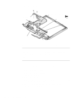
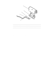
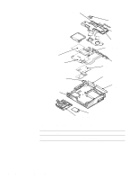
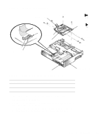
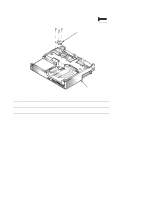
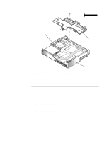
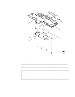
Diskette/CD-ROM Drive Assembly connector JCDROM connector JFLOP CD-ROM flex cable D3 (2 mm) D9 (2 mm) D1 (4 mm) D4 (2 mm) plastic flip lock CD-ROM drive diskette drive D2 (4 mm) 4 mm bracket 2 mm D5 (2 mm) D8 (2 mm) D6 (2 mm) D7 (2 mm) tab Figure 4-23. Diskette/CD-ROM Drive Assembly Removal bottom case assembly Part or Assembly Name Diskette drive assembly CD-ROM drive assembly Order Name SVC,ASSY,FD,LXPiCD SVC,ASSY,CDROM,LXPiCD To remove the diskette/CD-ROM drive assembly, follow these steps: 1. Remove the palmrest assembly. 2. Remove screws D1 and D2 securing the diskette/CD-ROM drive assembly to the bottom case assembly. 3. Lift the back of the drive assembly slightly, and then slide the drive assembly toward the back of the computer about 1/4 of an inch Removing and Replacing Parts 4-31
-
 1
1 -
2
-
3
-
4
-
5
-
6
-
7
-
8
-
9
-
10
-
11
-
12
-
13
-
14
-
15
-
16
-
17
-
18
-
19
-
20
-
21
-
22
-
23
-
24
-
25
-
26
-
27
-
28
-
29
-
30
-
31
-
32
-
33
-
34
-
35
-
36
-
37
-
38
-
39
-
40
-
41
-
42
-
43
-
44
-
45
-
46
-
47
-
48
-
49
-
50
-
51
-
52
-
53
-
54
-
55
-
56
-
57
-
58
-
59
-
60
-
61
-
62
-
63
-
 64
64 -
 65
65 -
 66
66 -
 67
67 -
 68
68 -
 69
69 -
 70
70 -
 71
71 -
 72
72 -
 73
73 -
 74
74 -
75
-
76
-
77
-
78
-
79
-
80
-
81
-
82
-
83
-
84
-
85
-
86
-
87
-
88
-
89
-
90
-
91
-
92
-
93
-
94
-
95
-
96
-
97
-
98
-
99
-
100
-
101
-
102
-
103
-
104
-
105
-
106
-
107
-
108
-
109
-
110
-
111
-
112
-
113
-
114
-
115
-
116
-
117
-
118
-
119
-
120
-
121
-
122
 |
 |
