Dell PowerConnect B-8000 Reference Manual - Page 20
Cabinet installation for a PowerConnect B-8000, PowerConnect B-8000 configuration
 |
View all Dell PowerConnect B-8000 manuals
Add to My Manuals
Save this manual to your list of manuals |
Page 20 highlights
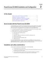
2 Cabinet installation for a PowerConnect B-8000 a. Clean the indentations at each corner of the bottom of the switch to ensure that they are free of dust or other debris that might lessen the adhesion of the feet. b. With the adhesive side against the chassis, place one rubber foot in each indentation and press into place. 3. Place the switch on a flat, sturdy surface. 4. Provide power to the switch as described in "Providing power to the switch" on page 8. ATTENTION Do not connect the switch to the network until the IP address is correctly set. For instructions on how to set the IP address, see "PowerConnect B-8000 configuration" Cabinet installation for a PowerConnect B-8000 Follow the installation instructions shipped with the appropriate rack mount kit: • To install the switch into a fixed-rail rack, refer to the Fixed Rack Mount Kit Installation Procedure. • To install the switch into mid-mount rack, refer to the Mid-Mount Rack Mount Kit (Switch) Installation Procedure. PowerConnect B-8000 configuration Once you have set up the PowerConnect B-8000 in a rack or as a standalone switch, it is time to give it power and a basic configuration. If you are going to use the PowerConnect B-8000 in a single-switch setup, you can use EZSwitchSetup to complete the basic configuration. See the EZSwitchSetup CD, included with the PowerConnect B-8000, for more information. You can also use the PowerConnect B-8000 Quick Start Guide. If you do not want to use EZSwitch Setup, follow the instructions in the rest of this section. NOTE The required configuration must be done from the Fibre Channel side. There are no specific instructions for configuring the CEE side of the switch. Providing power to the switch Perform the following steps to provide power to the PowerConnect B-8000. 1. Connect the power cords to both power supplies, and then to power sources on separate circuits to protect against AC failure. Ensure that the cords have a minimum service loop of 6 in. available and are routed to avoid stress. 2. Power on the power supplies by flipping both AC switches to the "I" symbol. The power supply LEDs display amber until POST is complete, and then change to green. The switch usually requires several minutes to boot and complete POST. 8 PowerConnect B-8000 Hardware Reference Manual 53-1001788-01
-
 1
1 -
2
-
3
-
4
-
5
-
6
-
7
-
8
-
9
-
10
-
11
-
12
-
13
-
14
-
 15
15 -
 16
16 -
 17
17 -
 18
18 -
 19
19 -
 20
20 -
 21
21 -
 22
22 -
 23
23 -
 24
24 -
 25
25 -
26
-
27
-
28
-
29
-
30
-
31
-
32
-
33
-
34
-
35
-
36
-
37
-
38
-
39
-
40
-
41
-
42
-
43
-
44
-
45
-
46
-
47
-
48
-
49
-
50
-
51
-
52
-
53
-
54
-
55
-
56
-
57
-
58
 |
 |