Dell PowerConnect B-8000 Reference Manual - Page 28
LED locations,
 |
View all Dell PowerConnect B-8000 manuals
Add to My Manuals
Save this manual to your list of manuals |
Page 28 highlights
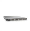
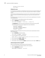
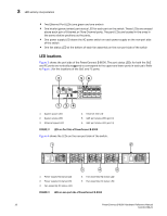
3 LED activity interpretation • Two Ethernet Port LEDs (one green and one amber) • One bicolor (green/amber) port status LED for each port on the switch. These LEDs are arrayed above each pair of Ethernet or Fibre Channel ports. The port LEDs are located in the array in the same relative positions as the ports. • One power supply LED above the AC power switch on each power supply on the non-port side of the switch • One fan status LED at the bottom of each fan assembly on the non-port side of the switch LED locations Figure 3 shows the port side of the PowerConnect B-8000. The port status LEDs for both the GbE and FC ports are vertically staggered to correspond to the upper and lower ports in each pair. Refer to Figure 1 for the locations of the GbE and FC ports. 2 56 1 34 1 System power LED 2 System status LED 3 Ethernet speed LED 4 Ethernet link LED 5 GbE port status LED (port 0) 6 GbE port status LED (port 4) FIGURE 3 LEDs on Port Side of PowerConnect B-8000 Figure 4 shows the LEDs on the non-port side of the switch. 1 2 3 4 5 1 Power supply #2 status LED 2 Power supply #1 status LED 3 Fan assembly #3 status LED 4 Fan assembly #2 status LED 5 Fan assembly #1 status LED FIGURE 4 LEDs on non-port side of PowerConnect B-8000 16 PowerConnect B-8000 Hardware Reference Manual 53-1001788-01
-
 1
1 -
2
-
3
-
4
-
5
-
6
-
7
-
8
-
9
-
10
-
11
-
12
-
13
-
14
-
15
-
16
-
17
-
18
-
19
-
20
-
21
-
22
-
 23
23 -
 24
24 -
 25
25 -
 26
26 -
 27
27 -
 28
28 -
 29
29 -
 30
30 -
 31
31 -
 32
32 -
 33
33 -
34
-
35
-
36
-
37
-
38
-
39
-
40
-
41
-
42
-
43
-
44
-
45
-
46
-
47
-
48
-
49
-
50
-
51
-
52
-
53
-
54
-
55
-
56
-
57
-
58
 |
 |