Dell PowerConnect B-8000 Reference Manual - Page 42
Replacing a PowerConnect B-8000 fan assembly, Table 5
 |
View all Dell PowerConnect B-8000 manuals
Add to My Manuals
Save this manual to your list of manuals |
Page 42 highlights
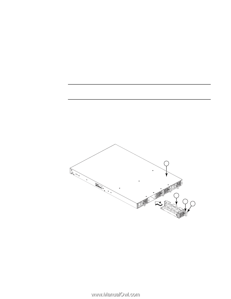
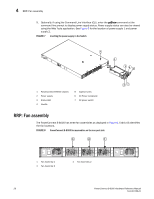
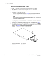
4 RRP: Fan assembly Replacing a PowerConnect B-8000 fan assembly To replace a fan assembly in the PowerConnect B-8000, complete the following steps. 1. With a Phillips-head screwdriver, unscrew the captive screw on the fan assembly. 2. Pull the fan assembly out by the handle, away from the chassis. 3. Install the new fan assembly in the chassis: a. Orient the new fan assembly as shown in Figure 9, with the captive screw on the right. b. Gently push the fan assembly into the chassis until it is firmly seated. NOTE Do not force the installation. If the fan assembly does not slide in easily, ensure that it is correctly oriented before continuing. c. Using the Phillips-head screwdriver, secure the fan assembly to the chassis by tightening in the captive screw. 4. Verify that the fan status LED is lit (steady green) to indicate normal operation (see Table 5). 5. Optionally, if using the Command Line Interface (CLI), display the fan status using the fanShow command from the command line. The fan status can be also be viewed using the Web Tools application. See Figure 8 for the locations of the fan assemblies. FIGURE 9 Inserting the fan assembly in the PowerConnect B-8000 1 1 PowerConnect B-8000 chassis 2 Fan Assembly 3 Captive Screw 4 Handle 2 43 30 PowerConnect B-8000 Hardware Reference Manual 53-1001788-01
-
 1
1 -
2
-
3
-
4
-
5
-
6
-
7
-
8
-
9
-
10
-
11
-
12
-
13
-
14
-
15
-
16
-
17
-
18
-
19
-
20
-
21
-
22
-
23
-
24
-
25
-
26
-
27
-
28
-
29
-
30
-
31
-
32
-
33
-
34
-
35
-
36
-
 37
37 -
 38
38 -
 39
39 -
 40
40 -
 41
41 -
 42
42 -
 43
43 -
 44
44 -
 45
45 -
 46
46 -
 47
47 -
48
-
49
-
50
-
51
-
52
-
53
-
54
-
55
-
56
-
57
-
58
 |
 |