Dell PowerEdge T40 EMC Installation and Service Manual - Page 71
Entering the system Service Tag by using System Setup, Control panel, Removing the control panel
 |
View all Dell PowerEdge T40 manuals
Add to My Manuals
Save this manual to your list of manuals |
Page 71 highlights
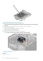
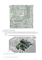
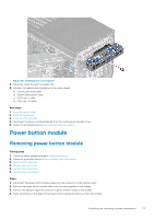
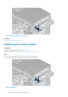
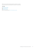
NOTE: Intel Active Management Technology (AMT) is supported only on Intel Xeon processor-based systems. NOTE: Intel Pentium/Core processor-based systems support Intel Standard Manageability. This procedure is used to update the service tag after a system board replacement. Steps 1. Remove the system cover. a) On the inside of the system cover near the System Information Label, note down the number on the AMT/VPRO QR code label. 2. Install the system cover. 3. Start the system. NOTE: If the system is powered on, shut the system down and start it up (cold boot). 4. After the system has started up, the Service Menu screen is displayed. 5. Select the number in AMT Options box corresponding to the AMT/VPRO number noted earlier from the system cover. NOTE: MANAGEABILITY ENGINE (ME) DISABLED and MANAGEABILITY ENGINE (ME) LOCKOUT are not supported on the PowerEdge T40. 6. Type the service tag information in the Enter Service Tag section. 7. Type the optional asset tag information in the Enter Asset Tag section. 8. Click OK to save the changes and exit. Entering the system Service Tag by using System Setup Steps 1. Turn on the system. 2. Press F2 to enter System Setup. 3. Click Service Tag Settings. 4. Enter the Service Tag. NOTE: You can enter the Service Tag only when the Service Tag field is empty. Ensure that you enter the correct Service Tag. After the Service Tag is entered, it cannot be updated or changed. 5. Click Ok. Control panel Removing the control panel Prerequisites 1. Follow the safety guidelines listed in Safety instructions. 2. Follow the procedure listed in Before working inside your system. 3. Disconnect all peripherals that are connected to the control panel. 4. Open the PSU assembly. 5. Remove the front bezel. 6. Remove the optical drive. Steps 1. Disconnect the cables mentioned below from the system board and unroute the cables from routing guides next to the system board on the chassis. a) Control panel audio cable. b) System board power cable. c) USB Type-C cable. Installing and removing system components 71
-
 1
1 -
2
-
3
-
4
-
5
-
6
-
7
-
8
-
9
-
10
-
11
-
12
-
13
-
14
-
15
-
16
-
17
-
18
-
19
-
20
-
21
-
22
-
23
-
24
-
25
-
26
-
27
-
28
-
29
-
30
-
31
-
32
-
33
-
34
-
35
-
36
-
37
-
38
-
39
-
40
-
41
-
42
-
43
-
44
-
45
-
46
-
47
-
48
-
49
-
50
-
51
-
52
-
53
-
54
-
55
-
56
-
57
-
58
-
59
-
60
-
61
-
62
-
63
-
64
-
65
-
 66
66 -
 67
67 -
 68
68 -
 69
69 -
 70
70 -
 71
71 -
 72
72 -
 73
73 -
 74
74 -
 75
75 -
 76
76 -
77
-
78
-
79
-
80
-
81
-
82
-
83
-
84
-
85
-
86
-
87
-
88
-
89
-
90
-
91
-
92
-
93
-
94
-
95
 |
 |