Dell PowerEdge T40 EMC Installation and Service Manual - Page 73
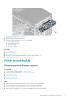
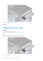
Power button module, Removing power button module
 |
View all Dell PowerEdge T40 manuals
Add to My Manuals
Save this manual to your list of manuals |
Page 73 highlights
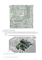
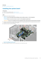
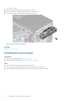
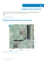
Figure 53. Installing the control panel 4. Route the cables through the system clip. 5. Connect the cables mentioned below to the system board. a) Control panel audio cable. b) System board power cable. c) USB Type-C cable. d) USB Type_A cables. Next steps 1. Install the optical Drive. 2. Install the front bezel. 3. Close the PSU assembly. 4. Reconnect the disconnected peripherals from the control panel assembly if any. 5. Follow the procedure listed in After working inside your system. Power button module Removing power button module Prerequisites 1. Follow the safety guidelines listed in Safety instructions. 2. Follow the procedure listed in Before working inside your system. 3. Open the PSU assembly. 4. Remove the front bezel. 5. Remove the optical drive. 6. Remove the control panel. Steps 1. Disconnect the power button module cable from the connector on the system board. 2. Remove the power button module cable from the routing guides on the chassis. 3. Remove the adhesive tape that secures the power button module to the chassis. 4. Press the latches on the sides of the power button module and remove it from the chassis. Installing and removing system components 73
-
 1
1 -
2
-
3
-
4
-
5
-
6
-
7
-
8
-
9
-
10
-
11
-
12
-
13
-
14
-
15
-
16
-
17
-
18
-
19
-
20
-
21
-
22
-
23
-
24
-
25
-
26
-
27
-
28
-
29
-
30
-
31
-
32
-
33
-
34
-
35
-
36
-
37
-
38
-
39
-
40
-
41
-
42
-
43
-
44
-
45
-
46
-
47
-
48
-
49
-
50
-
51
-
52
-
53
-
54
-
55
-
56
-
57
-
58
-
59
-
60
-
61
-
62
-
63
-
64
-
65
-
66
-
67
-
 68
68 -
 69
69 -
 70
70 -
 71
71 -
 72
72 -
 73
73 -
 74
74 -
 75
75 -
 76
76 -
 77
77 -
 78
78 -
79
-
80
-
81
-
82
-
83
-
84
-
85
-
86
-
87
-
88
-
89
-
90
-
91
-
92
-
93
-
94
-
95
 |
 |
