Dell Studio Hybrid Studio Slim Service Manual - Page 12
Replacing the Processor
 |
View all Dell Studio Hybrid Studio Slim manuals
Add to My Manuals
Save this manual to your list of manuals |
Page 12 highlights
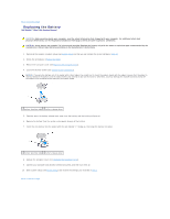
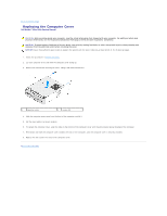
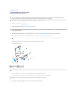
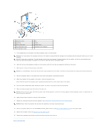
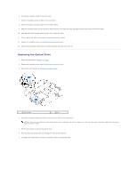
Back to Contents Page Replacing the Processor Dell Studio™ Slim 540s Service Manual CAUTION: Before working inside your computer, read the safety information that shipped with your computer. For additional safety best practices information, see the Regulatory Compliance Homepage at www.dell.com/regulatory_compliance. NOTICE: Do not perform the following steps unless you are familiar with hardware removal and replacement. Performing these steps incorrectly could damage your system board. To contact Dell for technical assistance, see the Setup Guide. 1. Follow the procedures in Before You Begin. 2. Remove the computer cover (see Replacing the Computer Cover). CAUTION: Despite having a plastic shield, the heat sink assembly may be very hot during normal operation. Be sure that it has had sufficient time to cool before you touch it. 3. Disconnect the power cables from the ATX POWER and ATX_CPU connectors (see System Board Components) on the system board. 4. Remove the processor fan and heat sink assembly (see Replacing the Processor Fan and Heat Sink Assembly). NOTE: Unless a new heat sink is required for the new processor, reuse the original heat sink assembly when you replace the processor. 5. Press and push the release lever down and out to release it from the tab that secures it. 6. Open the processor cover. 1 processor cover 2 processor 3 socket 4 release lever NOTICE: When removing or replacing the processor, do not touch any of the pins inside the socket or allow any objects to fall on the pins in the socket. 7. Lift up the processor to remove it from the socket, place it aside in a safe and secure place. Leave the release lever extended in the release position so that the socket is ready for the new processor. NOTICE: Ground yourself by touching an unpainted metal surface on the back of the computer. 8. Unpack the new processor, being careful not to touch the underside of the processor.
-
 1
1 -
2
-
3
-
4
-
5
-
6
-
 7
7 -
 8
8 -
 9
9 -
 10
10 -
 11
11 -
 12
12 -
 13
13 -
 14
14 -
 15
15 -
 16
16 -
 17
17 -
18
-
19
-
20
-
21
-
22
-
23
-
24
-
25
-
26
-
27
-
28
-
29
-
30
-
31
-
32
-
33
-
34
-
35
-
36
-
37
 |
 |