Dell Studio Hybrid Studio Slim Service Manual - Page 13
Replacing the Processor Fan and Heat Sink Assembly, System Board Components, Replacing the Computer
 |
View all Dell Studio Hybrid Studio Slim manuals
Add to My Manuals
Save this manual to your list of manuals |
Page 13 highlights
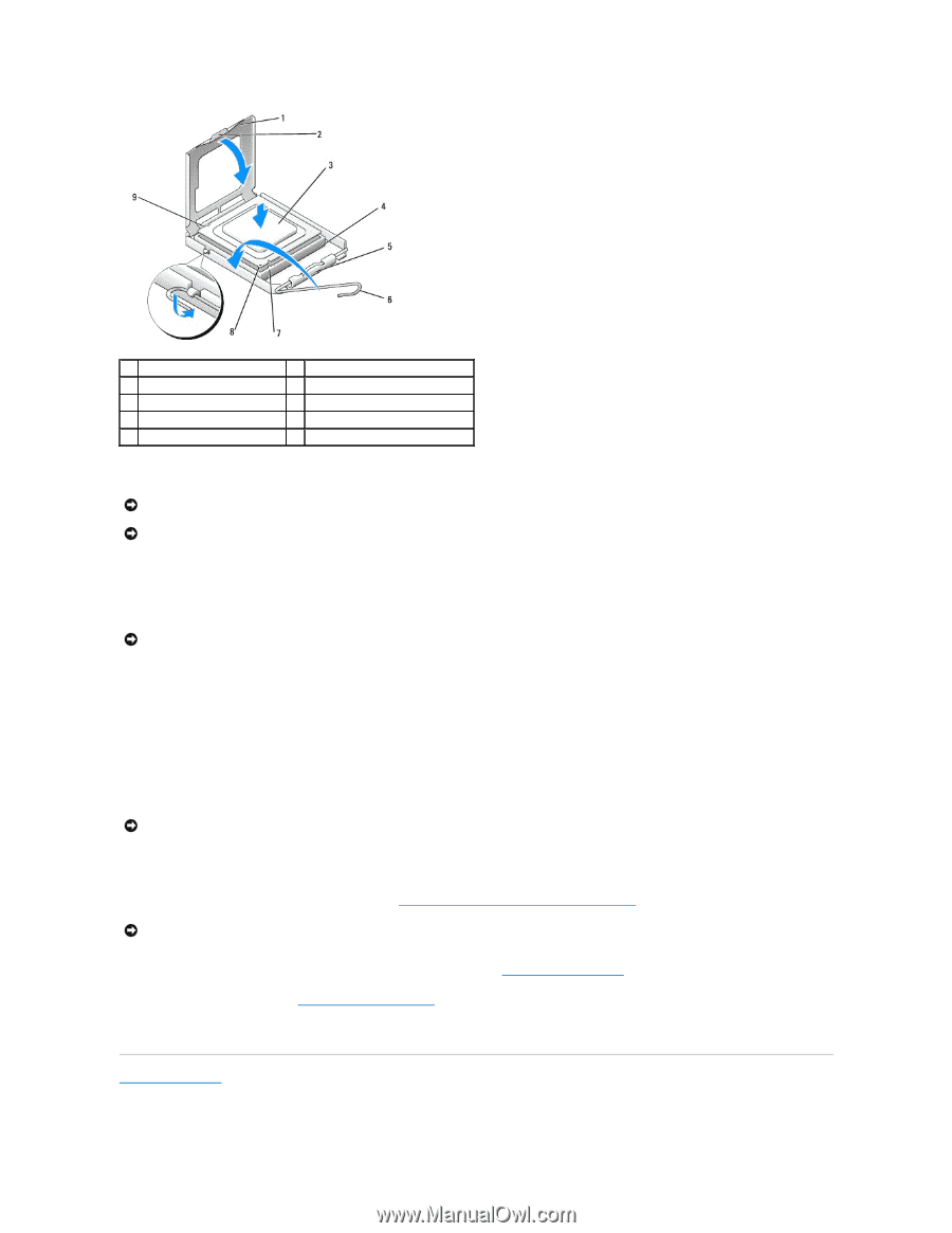
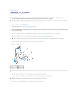
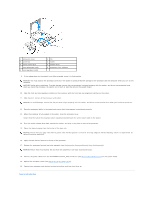
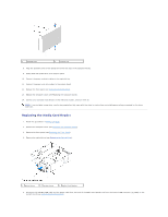
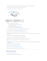
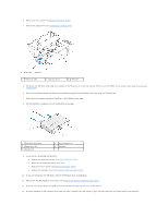
1 processor cover 3 processor 5 center cover latch 7 front alignment notch 9 rear alignment notch 2 tab 4 socket 6 release lever 8 processor pin-1 indicator 9. If the release lever on the socket is not fully extended, move it to that position. NOTICE: You must position the processor correctly in the socket to avoid permanent damage to the processor and the computer when you turn on the computer. NOTICE: Socket pins are delicate. To avoid damage, ensure that the processor is aligned properly with the socket, and do not use excessive force when you install the processor. Be careful not to touch or bend the pins on the system board. 10. Align the front and rear alignment-notches on the processor with the front and rear alignment-notches on the socket. 11. Align the pin-1 corners of the processor and socket. NOTICE: To avoid damage, ensure that the processor aligns properly with the socket, and do not use excessive force when you install the processor. 12. Place the processor lightly in the socket and ensure that the processor is positioned correctly. 13. When the processor is fully seated in the socket, close the processor cover. Ensure that the tab on the processor cover is positioned underneath the center cover latch on the socket. 14. Pivot the socket release lever back towards the socket, and snap it into place to secure the processor. 15. Clean the thermal grease from the bottom of the heat sink. NOTICE: Ensure that you apply new thermal grease. New thermal grease is critical for ensuring adequate thermal bonding, which is a requirement for optimal processor operation. 16. Apply the new thermal grease to the top of the processor. 17. Replace the processor fan and heat sink assembly (see Replacing the Processor Fan and Heat Sink Assembly). NOTICE: Ensure that the processor fan and heat sink assembly is correctly seated and secure. 18. Connect the power cables from the ATX POWER and ATX_CPU connectors (see System Board Components) on the system board. 19. Replace the computer cover (see Replacing the Computer Cover). 20. Connect your computer and devices to electrical outlets, and then turn them on. Back to Contents Page
-
 1
1 -
2
-
3
-
4
-
5
-
6
-
7
-
 8
8 -
 9
9 -
 10
10 -
 11
11 -
 12
12 -
 13
13 -
 14
14 -
 15
15 -
 16
16 -
 17
17 -
 18
18 -
19
-
20
-
21
-
22
-
23
-
24
-
25
-
26
-
27
-
28
-
29
-
30
-
31
-
32
-
33
-
34
-
35
-
36
-
37
 |
 |