Dell Studio Hybrid Studio Slim Service Manual - Page 18
Replacing the Front Panel, Replacing the Optical Drive, System Board, Components, Replacing
 |
View all Dell Studio Hybrid Studio Slim manuals
Add to My Manuals
Save this manual to your list of manuals |
Page 18 highlights
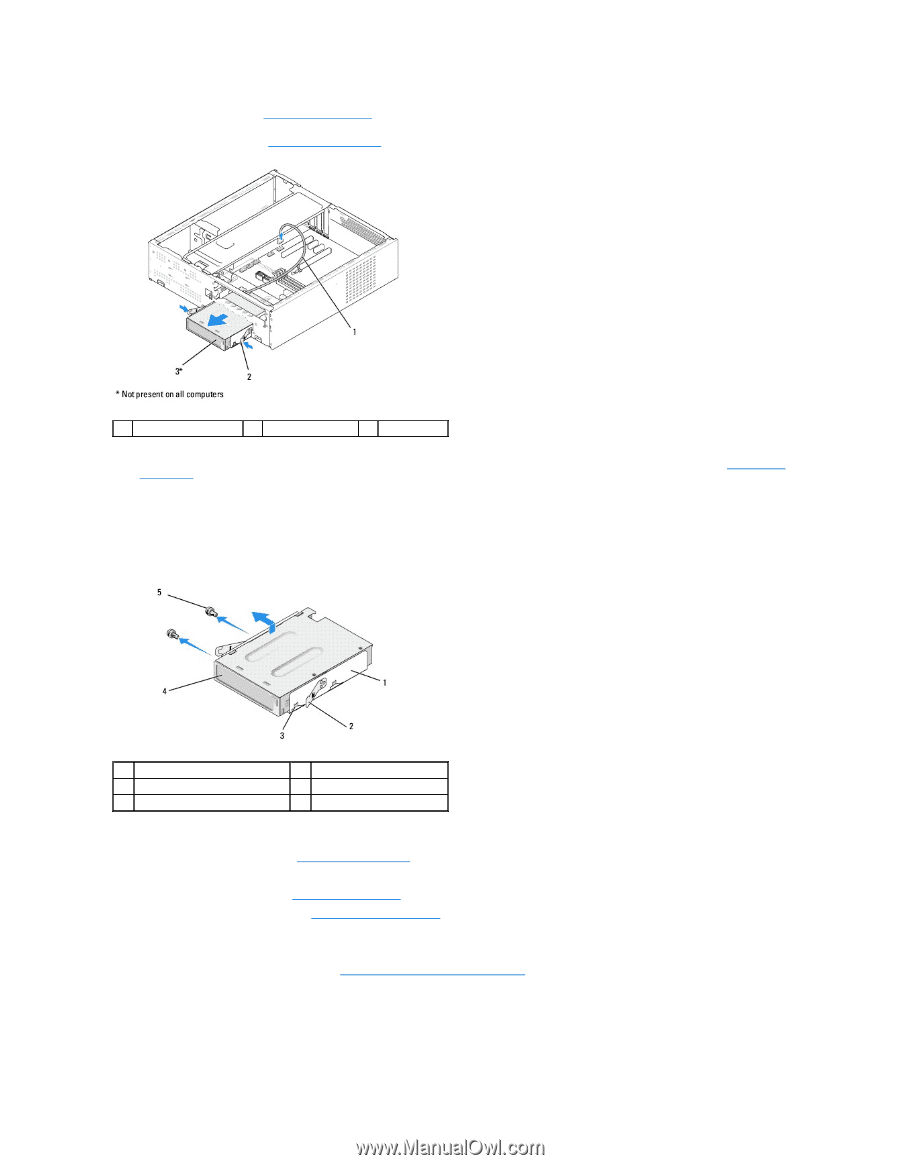
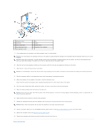
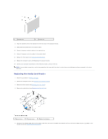
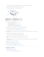
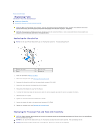
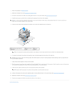
3. Remove the front panel (see Replacing the Front Panel). 4. Remove the optical drive (see Replacing the Optical Drive). 1 FlexDock cable 2 spring clamp 3 FlexDock 5. Disconnect the FlexDock USB cable from the back of the FlexDock and from the internal USB connector (F_USB1) on the system board (see System Board Components). 6. Press the two spring clamps and slide out the FlexDock along with the FlexDock drive cage from the FlexDock slot. 7. Remove the two screws holding the FlexDock in the FlexDock drive cage. 8. Lift the FlexDock to separate it from the FlexDock drive cage. 1 FlexDock drive cage 3 cage notch (2) 5 screws (2) 2 spring clamps (2) 4 FlexDock 9. If you are not reinstalling the FlexDock: a. Replace the optical drive (see Replacing the Optical Drive) b. Reinstall the FlexBay/FlexDock drive insert. c. Replace the front panel (see Replacing the Front Panel'). d. Replace the computer cover (see Replacing the Computer Cover). 10. If you are installing a new FlexDock, remove the FlexDock from its packaging. 11. Remove the FlexBay/FlexDock drive insert (see Replacing the FlexBay/FlexDock Drive Insert). 12. Press the two spring clamps and slide out the FlexDock drive cage from the front of the system. 13. Place the FlexDock in the FlexDock drive cage and slide it towards the cage notch to align the cage notch with the notch holes in the FlexDock.
-
 1
1 -
2
-
3
-
4
-
5
-
6
-
7
-
8
-
9
-
10
-
11
-
12
-
 13
13 -
 14
14 -
 15
15 -
 16
16 -
 17
17 -
 18
18 -
 19
19 -
 20
20 -
 21
21 -
 22
22 -
 23
23 -
24
-
25
-
26
-
27
-
28
-
29
-
30
-
31
-
32
-
33
-
34
-
35
-
36
-
37
 |
 |