Denon 4310CI Owners Manual - Page 23
Connections, Other, Devices
 |
UPC - 883795001014
View all Denon 4310CI manuals
Add to My Manuals
Save this manual to your list of manuals |
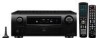
Page 23 highlights
LUMLM;Ii;iE u AM loop antenna assembly Remove the vinyl tie and take out the connection line. Bend in the reverse direction. Mount a. With the antenna on top of any stable surface. b. With the antenna attached to a wall. Connections to Other Devices Components Equipped with a DENON LINK Connector Multi-channel playback is possible with BD, Super Audio CD, etc. (Crpage 79 "Playing a Blu-ray Disc Player Compatible with DENON LINK 4th", "Playing Super Audio CD"). Blu-ray Disc player / DVD player AUDIO DENON LINK Connecting Devices Video Camera / Game Console Select the terminal to use and connect the device. For instructions on HDMI connections, see "Connecting Devices Equipped with HDM I Terminals" on page 14. Video camera / Game console VIDEO AUDIO . 1Prt, AUDIO OUT L R OPTICAOUT Installation hole Mount on wall, etc. Connection of AM antennas 1. Push the lever. 2. Insert the conductor. 3. Return the lever. i=> NOTE • Do not connect two FM antennas simultaneously. • Even if an external AM antenna is used, do not disconnect the AM loop antenna. ,0) • Make sure the AM loop antenna lead terminals do not touch metal parts of the panel. • • (0, \ • 10 0 O IO -612111=131 When connecting by use of DENON LINK, set "Digital" to "D.LINK". "Input Assign" (Cr page 47) II 0 0 0 -11211231=2111 Set this to change the input signal to which the input source is assigned. "Input Assign" (e 'page 46) 20
-
 1
1 -
2
-
3
-
4
-
5
-
6
-
7
-
8
-
9
-
10
-
11
-
12
-
13
-
14
-
15
-
16
-
17
-
 18
18 -
 19
19 -
 20
20 -
 21
21 -
 22
22 -
 23
23 -
 24
24 -
 25
25 -
 26
26 -
 27
27 -
 28
28 -
29
-
30
-
31
-
32
-
33
-
34
-
35
-
36
-
37
-
38
-
39
-
40
-
41
-
42
-
43
-
44
-
45
-
46
-
47
-
48
-
49
-
50
-
51
-
52
-
53
-
54
-
55
-
56
-
57
-
58
-
59
-
60
-
61
-
62
-
63
-
64
-
65
-
66
-
67
-
68
-
69
-
70
-
71
-
72
-
73
-
74
-
75
-
76
-
77
-
78
-
79
-
80
-
81
-
82
-
83
-
84
-
85
-
86
-
87
-
88
-
89
-
90
-
91
-
92
-
93
-
94
-
95
-
96
-
97
-
98
-
99
-
100
-
101
-
102
-
103
-
104
-
105
-
106
-
107
-
108
-
109
-
110
-
111
-
112
-
113
-
114
-
115
-
116
-
117
-
118
-
119
-
120
-
121
-
122
-
123
-
124
-
125
-
126
-
127
-
128
-
129
-
130
-
131
-
132
-
133
-
134
-
135
-
136
-
137
-
138
 |
 |
