Denon D-107 Owners Manual - Page 8
PART NAMES, FUNCTIONS AND DISPLAYS, CD receiver D-107, Speakers USC-107 and Subwoofer USW-107 - remote
 |
UPC - 081757504850
View all Denon D-107 manuals
Add to My Manuals
Save this manual to your list of manuals |
Page 8 highlights
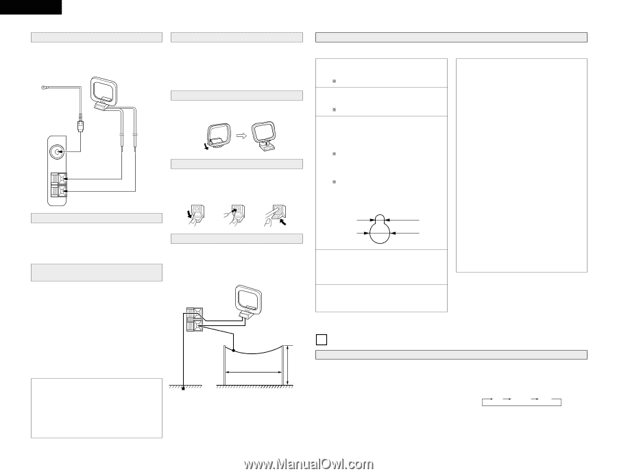
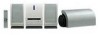
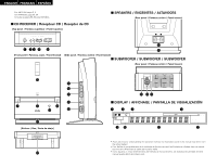
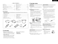
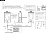
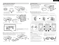
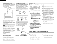
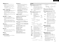
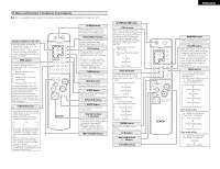
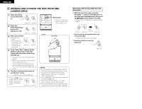
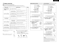
ENGLISH AN TTENNA AM GND FM COAX.75Ω AN TTENNA AM GND Installing the FM indoor antenna Tune in an FM station (see page 15), set the antenna in a position in which distortion and noise is minimum, then fasten the tip of the antenna in this position using tape or a pin. FM indoor antenna AM loop antenna Connecting an FM outdoor antenna If broadcasts cannot be tuned in clearly with the included antenna, use an outdoor FM antenna, connect a converter adapter to the coaxial cable and connect the converter adapter to the set's FM COAX (75 Ω/ohms) terminal. Selecting a place for the FM outdoor antenna • Set the antenna so that it is pointing towards the broadcast station's transmitting antenna. • Behind buildings or mountains, set the antenna in the position at which reception is best, and also try changing the direction of the antenna. • Do not install the antenna under power lines. Doing so is extremely dangerous, as the power line could touch the antenna. • Install the antenna away from roads or tracks to avoid noise from cars or trains. • Do not install the antenna too high, as it may be hit by lightning. Note to CATV system installer: This reminder is provided to Call the CATV system installer's attention to Article 820-40 of the NEC which provides guide lines for proper grounding and, in particular, specifies that the cable ground shall be connected to the grounding system of the building, as close to the point of cable entry as practical. Installing the AM loop antenna Tune in an AM station (see page 15), set the antenna in a position as far from the system as position in which distortion and noise is minimum. In some cases it is best to invert the polarities. AM broadcasts cannot be received well if the loop antenna is not connected or if it is set close to metal objects. Assembling the AM loop antenna Assemble the included AM loop antenna as shown in the diagram. Connecting the AM loop antenna Connect the included AM loop antenna to the antenna terminals as shown in the diagram. q Lower w Insert the e Return the the lever. antenna wire. lever. Installing an AM outdoor antenna Connect the signal wire from the AM outdoor antenna to the antenna terminal (ANTENNA AM). Be sure to ground the antenna and connect the ground wire to the GND terminal. Also be sure to connect the included AM loop antenna. Mounting on a wall 2 The D-107 and speakers (USC-107) can be mounted on a wall. 1 Connect the system cable to the bottom of the D-107. (See page 7.) There is no need to mount the stand. 2 Connect the cords to the speakers. (See page 7.) There is no need to mount the stand. 3 Mount the D-107 and speakers to the wall using commercially available screws and the holes on the rear panels of the D-107 and speakers. When mounting the screws on the wall, for convenience the included template can be used to determine the positions of the screws beforehand. Select screws referring to the diagram below. [Wall mount hole on rear panel of main unit and speakers] 4.2 mm 10 mm 4 Use the holes on the rear panels of the D-107 and the speakers to mount the D-107 and the speakers onto the screws in the wall. 5 Connect the system cable and speaker cords to the subwoofer. (See page 7.) NOTES: • When mounting on the wall, take care that no accidents occur due to the D-107 or speakers falling. • Check the wall surface before mounting the D107 and speakers to make sure it is strong enough to support the weight. • Consult a specialist if you do not know how strong the wall is. • Screws for mounting the D-107 on the wall are not included. Use screws suited to the strength and material of the pillar or wall. • Fasten the speaker cords and system cables in place so that there is no risk of them being pulled accidentally, causing the main unit or speakers to fall. • Be sure to mount using screws for all four screw holes on the CD receiver and both screw holes on the speakers. If any of the screw holes are not used, the CD receiver or speakers will be unstable and risk falling. • Do not install the CD receiver too high up. If the CD receiver is too high, the remote control signals may have not reach it easily, making it difficult to operate. • Note that Denon will not be held responsible for any accidents or damage due to improper assembly or mounting, insufficient mounting strength, erroneous usage, natural disasters, etc. Ground AM outdoor antenna Approx. 12 meters 4 PART NAMES, FUNCTIONS AND DISPLAYS 8 meters or greater (1) CD receiver (D-107), Speakers (USC-107) and Subwoofer (USW-107) q ON/STANDBY button • Press to button on the power and press again to set the standby mode. • The indicator color changes as follows, according to the condition: When in the power on mode: Green When in the standby mode: Red When in the timer standby mode: Orange When in standby in the eco-mode: Light off w FUNCTION button • Press this to select the function. • The function changes in the following order each time this button is pressed: CD TUNER AUX 8
-
 1
1 -
2
-
 3
3 -
 4
4 -
 5
5 -
 6
6 -
 7
7 -
 8
8 -
 9
9 -
 10
10 -
 11
11 -
 12
12 -
 13
13 -
14
-
15
-
16
-
17
-
18
-
19
-
20
-
21
-
22
-
23
-
24
-
25
-
26
-
27
-
28
-
29
-
30
-
31
-
32
-
33
-
34
-
35
-
36
-
37
-
38
-
39
-
40
-
41
-
42
-
43
-
44
-
45
-
46
-
47
-
48
-
49
-
50
-
51
-
52
-
53
-
54
-
55
-
56
-
57
-
58
-
59
-
60
-
61
-
62
-
63
-
64
-
65
-
66
-
67
-
68
-
69
-
70
-
71
-
72
-
73
-
74
-
75
-
76
-
77
-
78
-
79
-
80
 |
 |