Dewalt DHS790AT2 Instruction Manual - Page 10
Familiarization, COMPONENTS Fig. 4
 |
View all Dewalt DHS790AT2 manuals
Add to My Manuals
Save this manual to your list of manuals |
Page 10 highlights
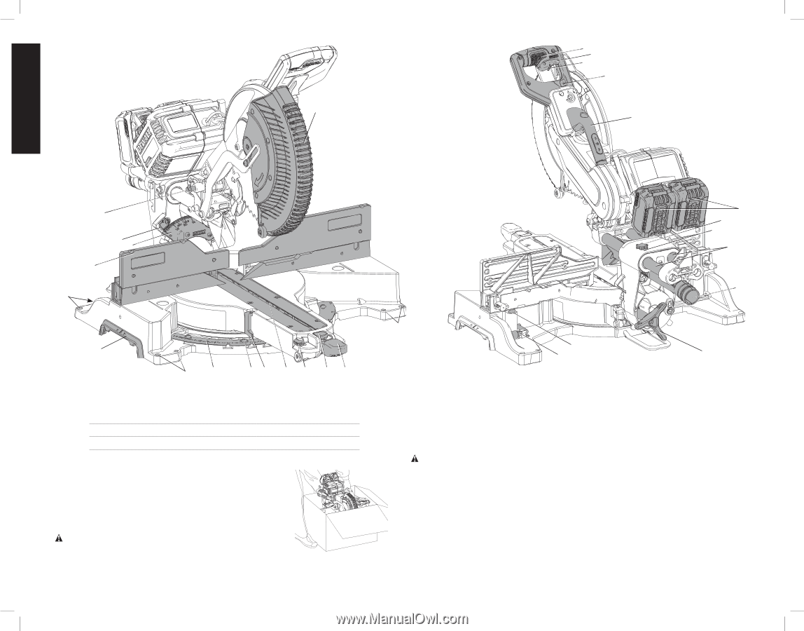
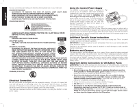
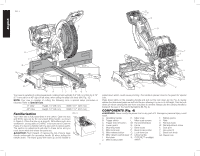
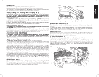
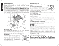
English FIG. 4 D A B C S R Q P O N E T V W U X E M AA Y Z E K LJ I H G F Your saw is capable of cutting baseboard moldings held vertically 0.8" (20 mm) thick by 6.75" (171 mm) tall on a 45º right or left miter, when using the slide lock lever (AN, Fig. 10). NOTE: Your saw is capable of cutting the following once a special setup procedure is followed. Refer to Special Cuts. 0° miter Height 1.5" (38 mm) Width 16.1" (409 mm) 45º miter Height 1.5" (38 mm) Width 11.7" (297 mm) Familiarization Your miter saw is fully assembled in the carton. Open the box and lift the saw out by the convenient lifting handle, as shown in Figure 5. Place the saw on a smooth, flat surface such as a workbench, strong table or DeWALT miter saw stand. Examine Figure 4 to become familiar with the saw and its various parts. The section on adjustments will refer to these terms and you must know what and where the parts are. CAUTION: Pinch Hazard. To reduce the risk of injury, keep thumb underneath the operating handle (A) when pulling the handle down. The lower guard will move up as the handle is FIG. 5 pulled down which could cause pinching. The handle is placed close to the guard for special cuts. Press down lightly on the operating handle and pull out the lock down pin (Q, Fig. 4). Gently release the downward pressure and hold the arm allowing it to rise to its full height. Use the lock down pin when carrying the saw from one place to another. Always use the carrying handle to transport the saw or the hand indentations (M, Fig. 4). COMPONENTS (Fig. 4) WARNING: Never modify the power tool or any part of it. Damage or personal injury could result. A. Operating handle K. Miter scale T. Battery packs B. Trigger switch L. Miter scale screws U. Rails C. Trigger lock-off button M. Hand indentations V. Rail lock knob D. Lower guard N. Fence W. Rail adjustment screw E. Mounting holes O. Bevel scale X. Dust port F. Miter lock lever P. Bevel scale pointer Y. Hex wrench G. Miter release button Q. Lock down pin Z. Bevel lock knob H. Miter detent override lever R. Lifting handle AA. Clamp hole I. Kerf plate S. CUTLINE™ worklight J. Miter scale pointer switch 8
-
 1
1 -
2
-
3
-
4
-
 5
5 -
 6
6 -
 7
7 -
 8
8 -
 9
9 -
 10
10 -
 11
11 -
 12
12 -
 13
13 -
 14
14 -
 15
15 -
16
-
17
-
18
-
19
-
20
-
21
-
22
-
23
-
24
-
25
-
26
-
27
-
28
-
29
-
30
-
31
-
32
-
33
-
34
-
35
-
36
-
37
-
38
-
39
-
40
-
41
-
42
-
43
-
44
-
45
-
46
-
47
-
48
-
49
-
50
-
51
-
52
-
53
-
54
-
55
-
56
-
57
-
58
-
59
-
60
-
61
-
62
-
63
-
64
-
65
-
66
-
67
-
68
-
69
-
70
-
71
-
72
-
73
-
74
-
75
-
76
 |
 |