Dewalt DHS790AT2 Instruction Manual - Page 12
ASSEMBLY, Bench Mounting, Changing or Installing a New Saw Blade Fig. 11
 |
View all Dewalt DHS790AT2 manuals
Add to My Manuals
Save this manual to your list of manuals |
Page 12 highlights
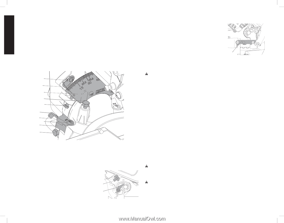
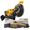
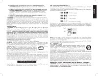
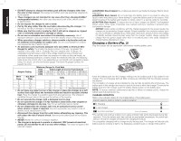
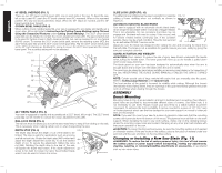
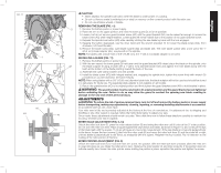
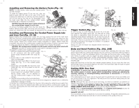
English 45° BEVEL OVERRIDE (FIG. 7) There are two 45° bevel override levers (AC), one on each side of the saw. To bevel the saw, left or right, past 45°, push the 45° bevel override lever (AC) rearward. When in the rearward position, the saw can bevel past these stops. When the 45° stops are needed, pull the 45° bevel override lever forward. CROWN BEVEL PAWLS (FIG. 8) When cutting crown molding laying flat, your saw is equipped to accurately and rapidly set a crown stop, left or right (refer to Instructions for Cutting Crown Molding Laying Flat and Using the Compound Features under Cutting Crown Molding). The 33.9° crown bevel pawl (AD) can be rotated to contact the crown adjustment screw (AF). The saw is factory set to be used for typical crown in North America (52/38), but can be reversed to cut non-typical (45/45) crown. To reverse the 33.9° crown bevel pawl, remove the retaining screw (AG), the 22.5° bevel pawl (AE) and the 33.9° crown bevel pawl (AD). Flip the 33.9° crown bevel pawl so the 30° text is facing up. Reattach the screw to secure the 22.5° bevel pawl and the crown bevel pawl. The accuracy setting will not be affected. FIG. 8 AJ P O AI AF AB AE AG AD AH 22.5° BEVEL PAWLS (FIG. 8) Your saw is equipped to rapidly and accurately set a 22.5° bevel, left or right. The 22.5° bevel pawl (AE) can be rotated to contact the crown adjustment screw (AF). RAIL LOCK KNOB (FIG. 4) The rail lock knob (V) allows you to lock the saw head firmly to keep it from sliding on the rails. This is necessary when making certain cuts or when transporting the saw. DEPTH STOP (FIG. 9) The depth stop allows the depth of cut of the blade to be limited. The stop is useful for applications such as grooving and tall vertical cuts. Rotate the depth stop (AK) forward and adjust the depth adjustment screw (AL) to set the desired depth of cut. To secure the adjustment, tighten the wing nut (AM). Rotating the depth stop to the rear of the saw will bypass the depth stop feature. If the depth adjustment screw is too tight to loosen by hand, the provided blade wrench can be used to loosen the screw. FIG. 9 AM AL AK SLIDE LOCK LEVER (FIG. 10) The slide lock lever (AN) places the saw in a position to maximize cutting of base molding when cut vertically as shown in Figure 25. FIG. 10 AUTOMATIC ELECTRIC BLADE BRAKE Your saw is equipped with an automatic electric blade brake which stops the saw blade within 5 seconds of trigger release. This is not adjustable. On rare occasions the brake may not engage and the blade will coast to a stop. If this occurs, wait for several minutes before continuing use. If the condition persists, there may be a fault condition. Have the tool serviced by an authorized DeWALT service center. AN Always be sure the blade has stopped before raising the arm and removing the blade from the kerf plate. The brake is not a substitute for guards. Ensure your own safety by giving the saw your complete attention. GUARD ACTUATION AND VISIBILITY CAUTION: Pinch Hazard. To reduce the risk of injury, keep thumb underneath the handle when pulling the handle down. The lower guard will move up as the handle is pulled down which could cause pinching. The blade guard on your saw has been designed to automatically raise when the arm is brought down and to lower over the blade when the arm is raised. The guard can be raised by hand when installing or removing saw blades or for inspection of the saw. NEVER RAISE THE BLADE GUARD MANUALLY UNL ESS THE SAW IS TURNED OFF. NOTE: Certain special cuts of large material will require that you manually raise the guard. Refer to Cutting Large Material under Special Cuts. The front section of the guard is louvered for visibility while cutting. Although the louvers dramatically reduce flying debris, they are openings in the guard and safety glasses should be worn at all times when viewing through the louvers. ASSEMBLY Bench Mounting Mounting holes (E, Fig. 4) are provided in all 4 feet to facilitate bench mounting. (Two differentsized holes are provided to accommodate different sizes of screws. Use either hole, it is not necessary to use both.) Always mount your saw firmly to a stable surface to prevent movement. To enhance the tool's portability, it can be mounted to a piece of 1/2" (12.7 mm) or thicker plywood which can then be clamped to your work support or moved to other job sites and reclamped. NOTE: If you elect to mount your saw to a piece of plywood, make sure that the mounting screws don't protrude from the bottom of the wood. The plywood must sit flush on the work support. When clamping the saw to any work surface, clamp only on the clamping bosses where the mounting screw holes are located. Clamping at any other point will interfere with the proper operation of the saw. CAUTION: To prevent binding and inaccuracy, be sure the mounting surface is not warped or otherwise uneven. If the saw rocks on the surface, place a thin piece of material under one saw foot until the saw sits firmly on the mounting surface. Changing or Installing a New Saw Blade (Fig. 11) WARNING: To reduce the risk of serious personal injury, turn tool off and remove the battery packs or power supply before transporting, making any adjustments, cleaning, repairing, or removing/installing attachments or accessories. An accidental start-up can cause injury. 10
-
 1
1 -
2
-
3
-
4
-
5
-
6
-
 7
7 -
 8
8 -
 9
9 -
 10
10 -
 11
11 -
 12
12 -
 13
13 -
 14
14 -
 15
15 -
 16
16 -
 17
17 -
18
-
19
-
20
-
21
-
22
-
23
-
24
-
25
-
26
-
27
-
28
-
29
-
30
-
31
-
32
-
33
-
34
-
35
-
36
-
37
-
38
-
39
-
40
-
41
-
42
-
43
-
44
-
45
-
46
-
47
-
48
-
49
-
50
-
51
-
52
-
53
-
54
-
55
-
56
-
57
-
58
-
59
-
60
-
61
-
62
-
63
-
64
-
65
-
66
-
67
-
68
-
69
-
70
-
71
-
72
-
73
-
74
-
75
-
76
 |
 |