Dewalt DHS790AT2 Instruction Manual - Page 14
Operation - lowes
 |
View all Dewalt DHS790AT2 manuals
Add to My Manuals
Save this manual to your list of manuals |
Page 14 highlights
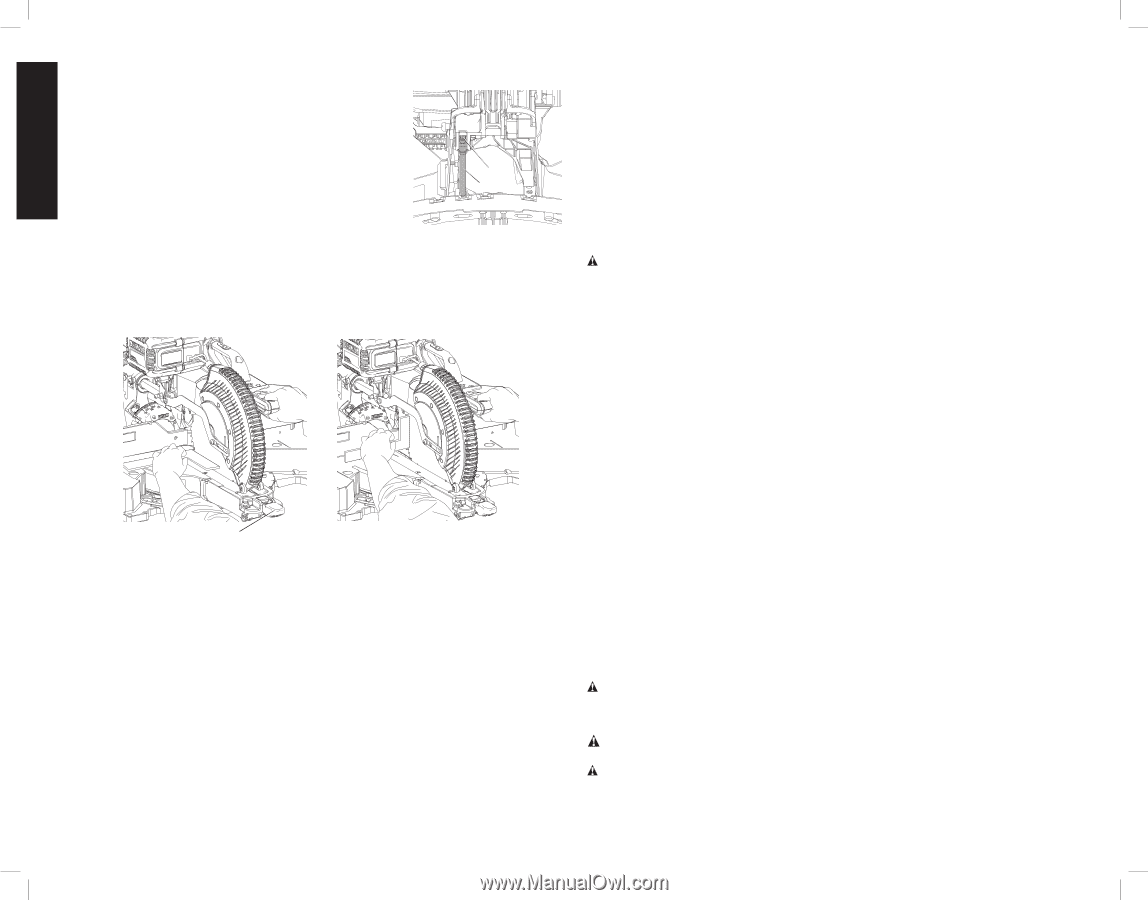
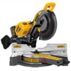
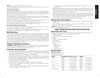
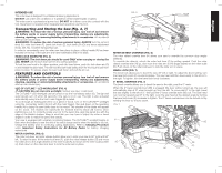
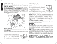
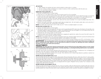
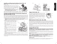
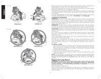
English MITER LOCK ADJUSTMENT (FIG. 6, 12) The miter lock rod (AX) should be adjusted if the table of the FIG. 12 saw can be moved when the miter lock lever (F) is locked (down). To adjust the miter lock, put the miter lock handle in the unlocked (up) position. Using a 1/2" open end wrench, loosen the lock nut (AY) on the miter lock rod (AX). Using a slotted screwdriver, tighten the miter lock rod by turning it clockwise. Turn the lock rod until it is snug, then turn counterclockwise one turn. To ensure the miter lock is AY functioning properly, re-lock the miter lock to a non-detented AX measurement on the miter scale - for example, 34º - and make sure the table will not rotate. Tighten lock nut. BEVEL SQUARE TO TABLE ADJUSTMENT (FIG. 4, 8, 13) To align the blade square to the table, lock the arm in the down position with the lock down pin. Place a square against the blade, ensuring the square is not on top of a tooth. Loosen the bevel lock knob (F) and ensure the arm is firmly against the 0° bevel stop. Rotate the 0° bevel adjustment screw (AI, Fig. 8) with the 1/2" blade wrench as necessary so that the blade is at 0° bevel to the table. FIG. 13 FIG. 14 F BEVEL POINTERS (FIG. 8) If the bevel pointers (P) do not indicate zero, loosen each bevel pointer screw (AJ) that holds each bevel pointer in place and move them as necessary. Ensure the 0° bevel is correct and the bevel pointers are set before adjusting any other bevel angle screws. BEVEL STOP 45º RIGHT AND LEFT ADJUSTMENT (FIG. 7, 8) There are two bevel stop override levers, one on each side of the saw. To adjust the right 45° bevel angle, loosen the bevel lock knob (Z) and pull the 0° bevel override lever (AB) to override the 0° bevel stop. When the saw is fully to the right, if the bevel pointer (P) does not indicate exactly 45°, turn the left 45° bevel adjustment screw (AH) with the 1/2" blade wrench until the bevel pointer indicates 45°. To adjust the left 45° bevel angle, first loosen the bevel lock knob (Z) and tilt the head to the left. If the bevel pointer (P) does not indicate exactly 45°, turn the right 45° bevel adjustment screw (AH) until the bevel pointer reads 45°. ADJUSTING THE BEVEL STOP TO 22.5° (OR 33.9°) (FIG. 7, 8) NOTE: Adjust the bevel angles only after performing the 0° bevel angle and bevel pointer adjustment. To set the left 22.5° bevel angle, flip out the left 22.5° bevel pawl (AE). Loosen the bevel lock knob (Z) and tilt the head fully to the left. If the bevel pointer (P) does not indicate exactly 22.5°, turn the crown adjustment screw (AF) contacting the pawl with a 7/16" wrench until the bevel pointer reads 22.5°. To adjust the right 22.5° bevel angle, flip out the right 22.5° bevel pawl (AE). Loosen the bevel lock knob (Z) and pull the 0° bevel override lever (AB) to override the 0° bevel stop. When the saw is fully to the right, if the bevel pointer (P) does not indicate exactly 22.5°, turn the crown adjustment screw (AF) contacting the pawl with a 7/16" wrench until the bevel pointer indicates exactly 22.5°. FENCE ADJUSTMENT (FIG. 7) WARNING: To reduce the risk of serious personal injury, turn tool off and remove the battery packs or power supply before transporting, making any adjustments, cleaning, repairing, or removing/installing attachments or accessories. An accidental start-up can cause injury. In order that the saw can bevel to many bevel positions, one of the fences (N) may have to be adjusted to provide clearance. To adjust each fence, loosen the fence adjustment knob (AZ) and slide the fence (N) outward. Make a dry run with the saw turned off and check for clearance. Adjust the fence to be as close to the blade as practical to provide maximum workpiece support, without interfering with arm up and down movement. Tighten the fence adjustment knob (AZ) securely. When the bevel operations are complete, don't forget to relocate the fence. For certain cuts, it may be desirable to bring the fences closer to the blade. To use this feature, back the fence adjustment knobs out two turns and move the fences closer to the blade past the normal limit, then tighten the fence adjustment knobs to keep the fences in this location. When using this feature, make a dry cut first to ensure the blade does not contact the fences. NOTE: The tracks of the fences can become clogged with sawdust. If you notice that they are becoming clogged, use a brush or some low pressure air to clear the guide grooves. KERF PLATE ADJUSTMENT (FIG. 4) To adjust the kerf plates (I), loosen the screws holding the kerf plates in place. Adjust so that the kerf plates are as close as possible without interfering with the blade's movement. If a zero kerf width is desired, adjust the kerf plates as close to each other as possible. They can now be cut slowly with the saw blade to give the smallest gap possible between the blade and the kerf plates. RAIL GUIDE ADJUSTMENT (FIG. 4) Periodically check the rails for any play or clearance. The right rail can be adjusted with the rail adjustment screw (W) shown in Figure 4. To reduce clearance, use a 4 mm hex wrench and rotate the rail adjustment screw clockwise gradually while sliding the saw head back and forth. Reduce play while maintaining minimum slide force. OPERATION WARNING: To reduce the risk of serious personal injury, turn tool off and remove the battery packs or power supply before transporting, making any adjustments, cleaning, repairing, or removing/installing attachments or accessories. An accidental start-up can cause injury. WARNING: Always use eye protection. All users and bystanders must wear eye protection that conforms to ANSI Z87.1 (CAN/CSA Z94.3). WARNING: To ensure the blade path is clear of obstructions, always make a dry run of the cut without power before making any cuts on the workpiece. 12
-
 1
1 -
2
-
3
-
4
-
5
-
6
-
7
-
8
-
 9
9 -
 10
10 -
 11
11 -
 12
12 -
 13
13 -
 14
14 -
 15
15 -
 16
16 -
 17
17 -
 18
18 -
 19
19 -
20
-
21
-
22
-
23
-
24
-
25
-
26
-
27
-
28
-
29
-
30
-
31
-
32
-
33
-
34
-
35
-
36
-
37
-
38
-
39
-
40
-
41
-
42
-
43
-
44
-
45
-
46
-
47
-
48
-
49
-
50
-
51
-
52
-
53
-
54
-
55
-
56
-
57
-
58
-
59
-
60
-
61
-
62
-
63
-
64
-
65
-
66
-
67
-
68
-
69
-
70
-
71
-
72
-
73
-
74
-
75
-
76
 |
 |