Dewalt DHS790AT2 Instruction Manual - Page 18
Cutting Compound Miters, Fig. 24, Cutting Base Molding Fig. 25, Cutting Crown Molding
 |
View all Dewalt DHS790AT2 manuals
Add to My Manuals
Save this manual to your list of manuals |
Page 18 highlights
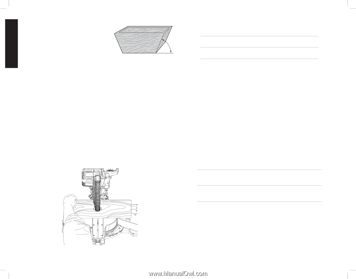
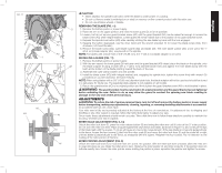
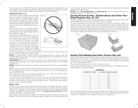
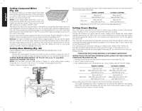
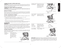
English Cutting Compound Miters FIG. 24 (Fig. 24) A compound miter is a cut made using a miter angle and a bevel angle at the same time. This is the type of cut used to make frames or boxes with slanting sides like the one shown in Figure 24. NOTE: If the cutting angle varies from cut to cut, check that the bevel lock knob and the miter lock handle are securely locked. These must be locked ANGLE "A" after making any changes in bevel or miter. The chart at the end of this manual (Table 1) will assist you in selecting the proper bevel and miter settings for common compound miter cuts. To use the chart, select the desired angle A (Fig. 24) of your project and locate that angle on the appropriate arc in the chart. From that point follow the chart straight down to find the correct bevel angle and straight across to find the correct miter angle. Set your saw to the prescribed angles and make a few trial cuts. Practice fitting the cut pieces together until you develop a feel for this procedure and feel comfortable with it. Example: To make a 4-sided box with 26º exterior angles (Angle A, Fig. 24), use the upper right arc. Find 26° on the arc scale. Follow the horizontal intersecting line to either side to get miter angle setting on saw (42°). Likewise, follow the vertical intersecting line to the top or bottom to get the bevel angle setting on the saw (18°). Always try cuts on a few scrap pieces of wood to verify the settings on the saw. Cutting Base Molding (Fig. 25) ALWAYS MAKE A DRY RUN WITHOUT POWER BEFORE MAKING ANY CUTS. Straight 90º cuts: Position the wood against the fence and hold it in place as shown in Figure 25. Turn on the saw, allow the blade to reach full speed and lower the arm smoothly through the cut. CUTTING BASE MOLDING FROM 3" UP TO 6.75" (76 mm to 171 mm) HIGH VERTICALLY AGAINST THE FENCE NOTE: Use the slide lock lever (AN), shown in Figure 10, when cutting base molding measuring from 3" to 6.75" (76 mm to 171 mm) high vertically against the fence. Position material as shown in Figure 25. FIG. 25 All cuts should be made with the back of the molding against the fence and with the bottom of the molding against the table. INSIDE CORNER OUTSIDE CORNER Left side Miter left 45° Save left side of cut Miter right 45° Save left side of cut Right side Miter right 45° Save right side of cut Miter left 45° Save right side of cut Material up to 6.75" (171 mm) can be cut as described above. Cutting Crown Molding Your miter saw is well suited to the task of cutting crown molding. In order to fit properly, crown molding must be compound mitered with extreme accuracy. The two flat surfaces on a given piece of crown molding are at angles that, when added together, equal exactly 90º. Most, but not all, crown molding has a top rear angle (the section that fits flat against the ceiling) of 52º and a bottom rear angle (the part that fits flat against the wall) of 38º. Your miter saw has special pre-set miter latch points at 31.62º left and right for cutting crown molding at the proper angle and bevel stop pawls at 33.9º left and right. There is also a mark on the bevel scale at 33.9º. The chart below gives the proper settings for cutting crown molding. (The numbers for the miter and bevel settings are very precise and are not easy to accurately set on your saw.) Since most rooms do not have angles of precisely 90º, you will have to fine tune your settings anyway. PRETESTING WITH SCRAP MATERIAL IS EXTREMELY IMPORTANT! INSTRUCTIONS FOR CUTTING CROWN MOLDING LAYING FLAT AND USING THE COMPOUND FEATURES (FIG. 26) 1. Molding should lay flat with broad back surface down on saw table (Fig. 26). 2. Top of molding against fence. 3. The settings below are for all standard (U.S.) crown molding with 52° and 38° angles. INSIDE CORNER OUTSIDE CORNER Left side Bevel left 33.9° Miter table set at right 31.62° Save left end of cut Bevel right 33.9° Miter table set at left 31.62° Save left end of cut Right side Bevel right 33.9° Miter table set at left 31.62° Save right end of cut Bevel left 33.9° Miter table set at right 31.62° Save right end of cut When setting bevel and miter angles for all compound miters, remember that: The angles presented for crown moldings are very precise and difficult to set exactly. Since they can easily shift slightly and very few rooms have exactly square corners, all settings should be tested on scrap molding. 16
-
 1
1 -
2
-
3
-
4
-
5
-
6
-
7
-
8
-
9
-
10
-
11
-
12
-
 13
13 -
 14
14 -
 15
15 -
 16
16 -
 17
17 -
 18
18 -
 19
19 -
 20
20 -
 21
21 -
 22
22 -
 23
23 -
24
-
25
-
26
-
27
-
28
-
29
-
30
-
31
-
32
-
33
-
34
-
35
-
36
-
37
-
38
-
39
-
40
-
41
-
42
-
43
-
44
-
45
-
46
-
47
-
48
-
49
-
50
-
51
-
52
-
53
-
54
-
55
-
56
-
57
-
58
-
59
-
60
-
61
-
62
-
63
-
64
-
65
-
66
-
67
-
68
-
69
-
70
-
71
-
72
-
73
-
74
-
75
-
76
 |
 |