Dewalt DHS790AT2 Instruction Manual - Page 13
Adjustments
 |
View all Dewalt DHS790AT2 manuals
Add to My Manuals
Save this manual to your list of manuals |
Page 13 highlights
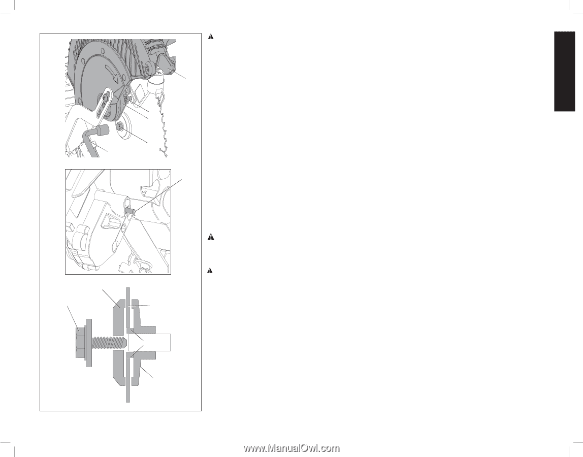
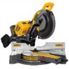
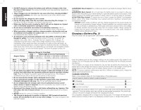
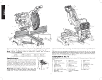
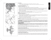
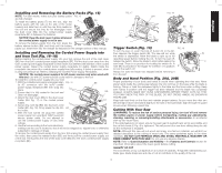
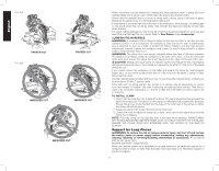
FIG. 11 Y AS AQ AP AO AQ AT AU AV CAUTION: • Never depress the spindle lock button while the blade is under power or coasting. • Do not cut ferrous metal (containing iron or steel) or masonry or fiber cement product with this miter saw. • Do not use abrasive wheels or blades. REMOVING THE BLADE (FIG. 11) D 1. Remove the battery packs or power supply. 2. Raise the arm to the upper position and raise the lower guard (D) as far as possible. 3. Loosen, but do not remove guard bracket screw (AP) until the guard bracket (AO) can be raised far enough to access the blade screw (AQ) (with integral washer). Lower guard will remain raised due to the position of the guard bracket screw. 4. Depress the spindle lock button (AR) while carefully rotating the saw blade by hand until the lock engages. 5. Keeping the button depressed, use the other hand and the wrench provided (Y) to loosen the blade screw (AQ). (Turn clockwise, left-hand threads.) 6. Remove the blade screw (AQ), outer blade washer (AS) and blade (AT). The inner blade washer (AV), and if used, the 1" (25.4 mm) blade adapter (AU), may be left on the spindle. NOTE: For blades with a blade hole of 5/8" (15.88 mm), the 1" (25.4 mm) blade adapter is not used. INSTALLING A BLADE (FIG. 11) 1. Remove the battery packs or power supply. 2. With the arm raised, the lower guard (D) held open and the guard bracket (AO) raised, place the blade on the spindle, onto AR the blade adapter (if using a blade with a 1" [25.4 mm] diameter blade hole) and against the inner blade clamp with the teeth at the bottom of the blade pointing toward the back of the saw. 3. Assemble the outer clamp washer onto the spindle. 4. Install the blade screw (AQ) (with integral washer) and, engaging the spindle lock, tighten the screw firmly with wrench (Y) provided (turn counterclockwise, left-hand threads). NOTE: When using blades with a 5/8" (15.88 mm) diameter blade hole, the blade adapter will not be used and should be stored in a safe place for future use. The separate blade adapter is not available on all models. 5. Return the guard bracket (AO) to its original position and firmly tighten the guard bracket screw (AP) to hold bracket in place. WARNING: The guard bracket must be returned to its original position and the guard bracket screw tightened before activating the saw. Failure to do so may allow the guard to contact the spinning saw blade resulting in damage to the saw and severe personal injury. ADJUSTMENTS WARNING: To reduce the risk of serious personal injury, turn tool off and remove the battery packs or power supply before transporting, making any adjustments, cleaning, repairing, or removing/installing attachments or accessories. An accidental start-up can cause injury. Your miter saw is fully and accurately adjusted at the factory at the time of manufacture. If readjustment due to shipping and handling or any other reason is required, follow the instructions below to adjust your saw. Once made, these adjustments should remain accurate. Take a little time now to follow these directions carefully to maintain the accuracy of which your saw is capable. MITER SCALE ADJUSTMENT (FIG. 6, 14) Unlock the miter lock lever (F), press the miter release button (G) and swing the miter arm until it locks at the 0° miter position. Do not lock the miter lock lever. Place a square against the saw's fence and blade, as shown in Figure 14. (Do not touch the tips of the blade teeth with the square. To do so will cause an inaccurate measurement.) If the saw blade is not exactly perpendicular to the fence, loosen the four screws (L) that hold the miter scale (K) and move the miter lock lever (F) and the scale left or right until the blade is perpendicular to the fence, as measured with the square. Retighten the four screws. Pay no attention to the reading of the miter pointer at this time. MITER POINTER ADJUSTMENT (FIG. 6) Unlock the miter lock lever (F) to move the miter arm to the zero position. With the miter lock lever unlocked, allow the miter arm to snap into place as you rotate the miter arm to zero. Observe the miter pointer (J) and miter scale (K). If the pointer does not indicate exactly zero, loosen the miter pointer screw holding the pointer in place, reposition the pointer and tighten the screw. 11 English
-
 1
1 -
2
-
3
-
4
-
5
-
6
-
7
-
 8
8 -
 9
9 -
 10
10 -
 11
11 -
 12
12 -
 13
13 -
 14
14 -
 15
15 -
 16
16 -
 17
17 -
 18
18 -
19
-
20
-
21
-
22
-
23
-
24
-
25
-
26
-
27
-
28
-
29
-
30
-
31
-
32
-
33
-
34
-
35
-
36
-
37
-
38
-
39
-
40
-
41
-
42
-
43
-
44
-
45
-
46
-
47
-
48
-
49
-
50
-
51
-
52
-
53
-
54
-
55
-
56
-
57
-
58
-
59
-
60
-
61
-
62
-
63
-
64
-
65
-
66
-
67
-
68
-
69
-
70
-
71
-
72
-
73
-
74
-
75
-
76
 |
 |