Dewalt DHS790AT2 Instruction Manual - Page 17
Cutting Picture Frames, Shadow Boxes And Other Four, Sided Projects Fig. 22, 23, Cutting Trim
 |
View all Dewalt DHS790AT2 manuals
Add to My Manuals
Save this manual to your list of manuals |
Page 17 highlights
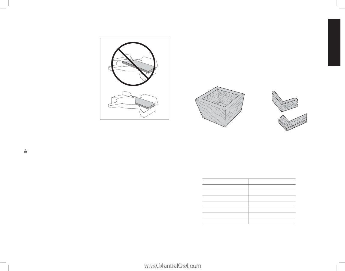
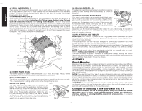
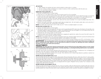
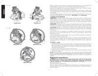
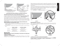
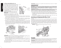
English For best results, use the DW7080 extension work support to extend the table width of your saw, available from your dealer at extra cost. Support long workpieces using any convenient means such as sawhorses or similar devices to keep the ends from dropping. CROSSCUTS (FIG. 4, 21) A crosscut is made by cutting wood across the FIG. 21 grain at any angle. A straight crosscut is made with the miter arm at the zero degree position. Set and lock the miter arm at zero, hold the wood firmly on the table and against the fence. With the rail lock knob (V) tightened, turn on the saw by squeezing the trigger switch shown in Figure 4. When the saw comes up to speed (about 1 second) lower the arm smoothly and slowly to cut through the wood. Let the blade come to a full stop before raising arm. When cutting anything larger than a 2 x 8 (51 x 203 mm [2 x 6 (51 x 152) at 45º miter]) use an out-down-back motion with the rail lock knob (V) loosened. Pull the saw out, toward you, lower the saw head down toward the workpiece, and slowly push the saw back to complete the cut. Do not allow the saw to contact the top of the workpiece while pulling out. The saw may run toward you, possibly causing personal injury or damage to the workpiece. Cutting of multiple pieces is not recommended but can be done safely by ensuring that each piece is held firmly against the table and fence. NOTE: To provide greater crosscut capacity with reduced stroke, the blade on the saw extends deeper into the table. As a result, a greater lifting force on the workpiece may be experienced during the cut. CAUTION: Always use a work clamp to maintain control and reduce the risk of workpiece damage and personal injury, if your hands are required to be within 6" (152 mm) of the blade during the cut. NOTE: The rail lock knob (V) shown in Figure 4 must be loose to allow the saw to slide along its rails. Miter crosscuts are made with the miter arm at some angle other than zero. This angle is often 45º for making corners, but can be set anywhere from zero to 50º left or 60° right. Make the cut as described above. When performing a miter cut on workpieces wider than a 2 x 6 that are shorter in length, always place the longer side against the fence (Fig. 21). To cut through an existing pencil line on a piece of wood, match the angle as close as possible. Cut the wood a little too long and measure from the pencil line to the cut edge to determine which direction to adjust the miter angle and recut. This will take some practice, but it is a commonly used technique. BEVEL CUTS A bevel cut is a crosscut made with the saw blade leaning at an angle to the wood. In order to set the bevel, loosen the bevel lock (V, Fig. 4), and move the saw to the left or right as desired. (It is necessary to move the fence to allow clearance.) Once the desired bevel angle has been set, tighten the bevel lock firmly. Refer to the Features and Controls section for detailed instructions on the bevel system. Bevel angles can be set from 49º right to 49º left and can be cut with the miter arm set between 50º left or 60º right. At some extreme angles, the right or left side fence might have to be removed. To remove the left or right fence, unscrew the fence adjustment knob several turns and slide the fence out. NOTE: Refer to Fence Adjustment in the Adjustments section for important information on adjusting the fences for certain bevel cuts. Cutting Picture Frames, Shadow Boxes And Other FourSided Projects (Fig. 22, 23) To best understand how to make the items listed here, we suggest that you try a few simple projects using scrap wood until you develop a "feel" for your saw. Your saw is the perfect tool for mitering corners like the one shown in Figure 22. Sketch A in Figure 23 shows a joint made by using the bevel adjustment to bevel the edges of the two boards at 45º each to produce a 90º corner. For this joint the miter arm was locked in the zero position and the bevel adjustment was locked at 45º. The wood was positioned with the broad flat side against the table and the narrow edge against the fence. The cut could also be made by mitering right and left with the broad surface against the fence. FIG. 22 FIG. 23 A B A Cutting Trim Molding And Other Frames (Fig. 23) Sketch B in Figure 23 shows a joint made by setting the miter arm at 45º to miter the two boards to form a 90º corner. To make this type of joint, set the bevel adjustment to zero and the miter arm to 45º. Once again, position the wood with the broad flat side on the table and the narrow edge against the fence. The two sketches in Figure 23 are for four-sided objects only. As the number of sides changes, so do the miter and bevel angles. The chart below gives the proper angles for a variety of shapes. - EXAMPLES - NUMBER OF SIDES MITER OR BEVEL ANGLE 4 45° 5 36° 6 30° 7 25.7° 8 22.5° 9 20° 10 18° The chart assumes that all sides are of equal length. For a shape that is not shown in the chart, use the following formula: 180º divided by the number of sides equals the miter (if the material is cut vertically) or bevel angle (if the material is cut laying flat). 15
-
 1
1 -
2
-
3
-
4
-
5
-
6
-
7
-
8
-
9
-
10
-
11
-
 12
12 -
 13
13 -
 14
14 -
 15
15 -
 16
16 -
 17
17 -
 18
18 -
 19
19 -
 20
20 -
 21
21 -
 22
22 -
23
-
24
-
25
-
26
-
27
-
28
-
29
-
30
-
31
-
32
-
33
-
34
-
35
-
36
-
37
-
38
-
39
-
40
-
41
-
42
-
43
-
44
-
45
-
46
-
47
-
48
-
49
-
50
-
51
-
52
-
53
-
54
-
55
-
56
-
57
-
58
-
59
-
60
-
61
-
62
-
63
-
64
-
65
-
66
-
67
-
68
-
69
-
70
-
71
-
72
-
73
-
74
-
75
-
76
 |
 |