Dewalt DHS790AT2 Instruction Manual - Page 11
Transporting and Storing the Saw Fig. 4, 7, FEATURES AND CONTROLS
 |
View all Dewalt DHS790AT2 manuals
Add to My Manuals
Save this manual to your list of manuals |
Page 11 highlights
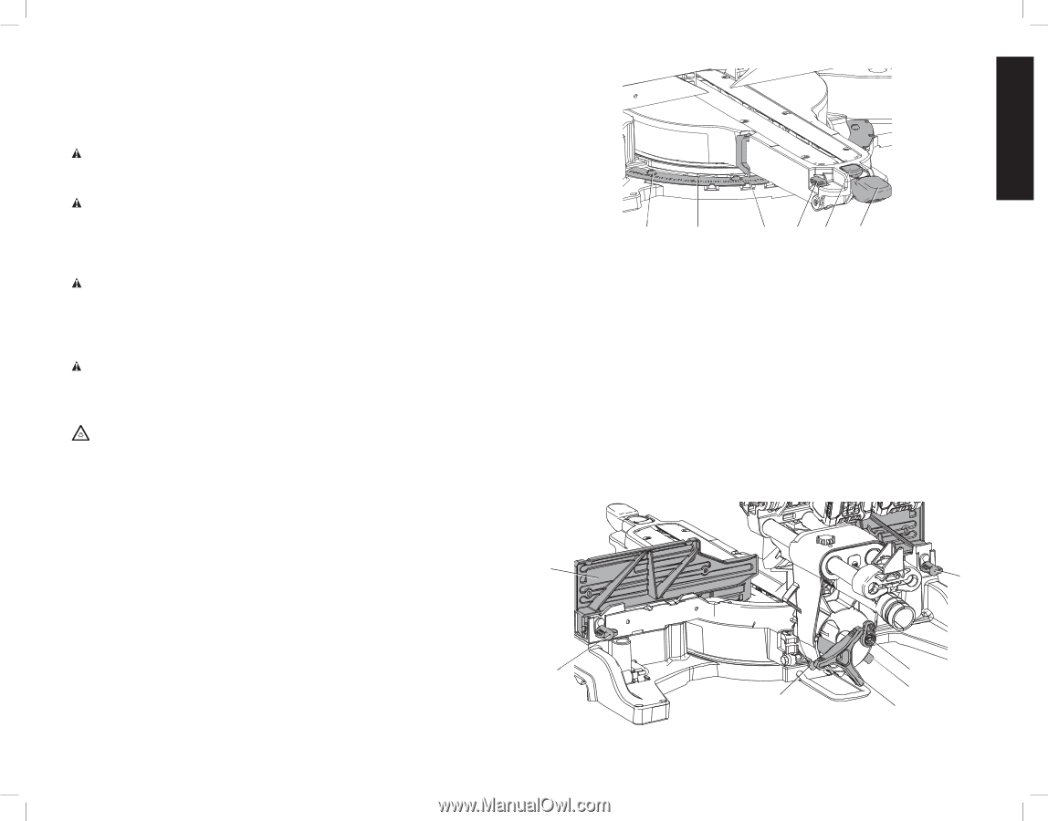
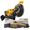
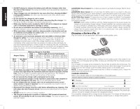
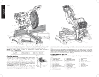
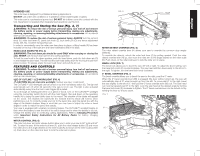
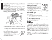
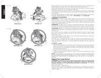
English INTENDED USE This miter saw is designed for professional sawing applications. DO NOT use under wet conditions or in presence of flammable liquids or gases. This miter saw is a professional power tool. DO NOT let children come into contact with the tool. Supervision is required when inexperienced operators use this tool. Transporting and Storing the Saw (Fig. 4, 7) WARNING: To reduce the risk of serious personal injury, turn tool off and remove the battery packs or power supply before transporting, making any adjustments, cleaning, repairing, or removing/installing attachments or accessories. An accidental start-up can cause injury. WARNING: To reduce the risk of serious personal injury, ALWAYS lock the rail lock knob (V), miter lock lever (F), bevel lock knob (Z), lock down pin (Q) and fence adjustment knobs (AZ, Fig. 7) before transporting saw. In order to conveniently carry the miter saw from place to place, a lifting handle (R) has been included on the top of the saw arm and hand indentations (M) in the base. HEAD LOCK DOWN PIN (FIG. 4) WARNING: The lock down pin should be used ONLY when carrying or storing the saw. NEVER use the lock down pin for any cutting operation. To lock the saw head in the down position, push the head down, push the lock down pin (Q) in and release the saw head. This will hold the saw head safely down for moving the saw from place to place. To release, press the saw head down and pull the pin out. FEATURES AND CONTROLS WARNING: To reduce the risk of serious personal injury, turn tool off and remove the battery packs or power supply before transporting, making any adjustments, cleaning, repairing, or removing/installing attachments or accessories. An accidental start-up can cause injury. USE OF CUTLINE™ LED WORKLIGHT (FIG. 4) CAUTION: Do not stare into worklight. Serious eye injury could result. The CUTLINE™ LED Worklight can be turned on by the momentary switch (S). The light will automatically turn off within 20 seconds if the saw is not in use. The light is also activated automatically every time the tool's main trigger (B) is pulled. To cut through an existing pencil line on a piece of wood, turn on the CUTLINE™ worklight using the momentary switch (S) (not with the main trigger), then pull down on the operating handle (A) to bring the saw blade close to the wood. The shadow of the blade will appear on the wood. This shadow line represents the material that the blade will remove when performing a cut. To correctly locate your cut to the pencil line, align the pencil line with the edge of the blade's shadow. Keep in mind that you may have to adjust the miter or bevel angles in order to match the pencil line exactly. Your saw is equipped with a battery monitoring feature. The CUTLINE™ worklight begins to flash when the battery is near the end of its useful charge and/or when the battery is too hot. Charge the battery prior to continuing cutting applications. Refer to Charging Procedure under Important Safety Instructions for All Battery Packs for battery charging instructions. MITER CONTROL (FIG. 6) The miter lock lever and miter release button allow you to miter your saw to 60° right and 50° left. To miter the saw, lift the miter lock lever (F), push the miter release button (G) and move the miter arm to the angle desired on the miter scale (K) as shown at the miter scale pointer (J). Push down on the miter lock lever to lock the miter arm in place. FIG. 6 L K JHG F MITER DETENT OVERRIDE (FIG. 6) The miter detent override lever (H) allows your saw to override the common stop angles (detents). To override the detents, unlock the miter lock lever (F) by pulling upward. Push the miter detent override lever (H) up, and move the miter arm to the angle desired on the miter scale (K). Push down on the miter lock lever to lock the miter arm in place. BEVEL LOCK (FIG. 7) The bevel lock allows you to bevel the saw 49° left or right. To adjust the bevel setting, turn the bevel lock knob (Z) counterclockwise. The saw head will then bevel easily to the left or to the right. To tighten, turn the bevel lock knob clockwise. 0° BEVEL OVERRIDE (FIG. 7) The bevel override allows you to bevel the saw to the right, past the 0° mark. When the 0° bevel override lever (AB) is engaged (the lever will be turned up), the saw will automatically stop at 0° when brought up from the left. To move past 0° to the right, bevel the saw slightly to the left of 0°, then pull the 0° bevel override lever (AB) out. The saw head can now be beveled past 0° to the right. Lock the saw head at the desired angle by turning the bevel lock knob (Z) clockwise to tighten. The 0° bevel override lever can be locked out by twisting the lever so it faces down. FIG. 7 N AZ AZ AB AC AC Z 9
-
 1
1 -
2
-
3
-
4
-
5
-
 6
6 -
 7
7 -
 8
8 -
 9
9 -
 10
10 -
 11
11 -
 12
12 -
 13
13 -
 14
14 -
 15
15 -
 16
16 -
17
-
18
-
19
-
20
-
21
-
22
-
23
-
24
-
25
-
26
-
27
-
28
-
29
-
30
-
31
-
32
-
33
-
34
-
35
-
36
-
37
-
38
-
39
-
40
-
41
-
42
-
43
-
44
-
45
-
46
-
47
-
48
-
49
-
50
-
51
-
52
-
53
-
54
-
55
-
56
-
57
-
58
-
59
-
60
-
61
-
62
-
63
-
64
-
65
-
66
-
67
-
68
-
69
-
70
-
71
-
72
-
73
-
74
-
75
-
76
 |
 |