Fluke 8808A User Manual - Page 30
Meter. See Table 2-1.
 |
View all Fluke 8808A manuals
Add to My Manuals
Save this manual to your list of manuals |
Page 30 highlights
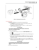
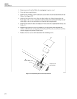
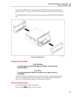
8808A Users Manual 1. Remove power from the Meter by unplugging its power cord. 2. Turn the Meter upside down. 3. Remove the retaining screw on the fuse access door located on the bottom of the Meter. See Figure 2-2. 4. Remove the protective cover from the fuse holders by slightly depressing the back edge of the cover to unlatch it from the printed circuit board. Pull up on the back edge of the cover and remove it from the fuse compartment. 5. Remove the defective fuse and replace it with a fuse of an appropriate rating. See Table 2-1. 6. Replace the protective cover by pushing it over the fuses while aligning the catches with the holes in the printed circuit board. Press the cover down until the catches engage the printed circuit board. 7. Replace the fuse access door and install the retaining screw. Fuses F2 F1 Bottom front left corner Figure 2-2. Replacing the Current-Input Fuses eue04.eps 2-6
-
 1
1 -
2
-
3
-
4
-
5
-
6
-
7
-
8
-
9
-
10
-
11
-
12
-
13
-
14
-
15
-
16
-
17
-
18
-
19
-
20
-
21
-
22
-
23
-
24
-
 25
25 -
 26
26 -
 27
27 -
 28
28 -
 29
29 -
 30
30 -
 31
31 -
 32
32 -
 33
33 -
 34
34 -
 35
35 -
36
-
37
-
38
-
39
-
40
-
41
-
42
-
43
-
44
-
45
-
46
-
47
-
48
-
49
-
50
-
51
-
52
-
53
-
54
-
55
-
56
-
57
-
58
-
59
-
60
-
61
-
62
-
63
-
64
-
65
-
66
-
67
-
68
-
69
-
70
-
71
-
72
-
73
-
74
-
75
-
76
-
77
-
78
-
79
-
80
-
81
-
82
-
83
-
84
-
85
-
86
-
87
-
88
-
89
-
90
-
91
-
92
-
93
-
94
-
95
-
96
-
97
-
98
-
99
-
100
 |
 |
