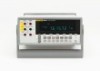
Fluke 8808A User Manual - Page 40
Dual Display, Primary Display, Secondary Display
 |
View all Fluke 8808A manuals
Add to My Manuals
Save this manual to your list of manuals |
Page 40 highlights
8808A Users Manual Dual Display The Meter has a 5-1/2 digit vacuum fluorescent dual display. See Figure 3-2 and Table 32 for an overview of the display annunciators and indicators The dual display is comprised of a primary display and a secondary display, which show measurement readings, annunciators and messages. The annunciators indicate measurement units and the Meter's operating configuration. The dual display allows you to see two properties for the input signal you are measuring. The Meter alternates between properties, measuring the first property and showing it on one display, and then measuring the second property and showing it on the other display. (For more detail, see the "How the Meter Takes Dual Display Measurements" section in Appendix A.) If an input exceeds the full-scale value of the selected range, the Meter displays 0Lto indicate an overload. Primary Display The primary display comprises the lower segment of the dual display, and consists of the larger digits and annunciators. The primary display shows measurements taken using the relative readings (REL), minimum maximum (MIN MAX), Touch Hold (HOLD), and decibels (dB) function modifiers. Secondary Display The secondary display comprises the upper segment of the dual display, and consists of the smaller digits and annunciators. Function modifiers REL, HOLD, MIN MAX, and dB and the manual range mode cannot be selected for the secondary display. The secondary display is either in autorange, or the same range as the primary display if both displays are in the the same function. 1 2 34 5 67 8 9 10 11 24 23 22 21 20 19 18 17 16 Figure 3-2. Display Annunciators and Indicators 12 13 14 15 eue01f.eps 3-6
-
 1
1 -
2
-
3
-
4
-
5
-
6
-
7
-
8
-
9
-
10
-
11
-
12
-
13
-
14
-
15
-
16
-
17
-
18
-
19
-
20
-
21
-
22
-
23
-
24
-
25
-
26
-
27
-
28
-
29
-
30
-
31
-
32
-
33
-
34
-
 35
35 -
 36
36 -
 37
37 -
 38
38 -
 39
39 -
 40
40 -
 41
41 -
 42
42 -
 43
43 -
 44
44 -
 45
45 -
46
-
47
-
48
-
49
-
50
-
51
-
52
-
53
-
54
-
55
-
56
-
57
-
58
-
59
-
60
-
61
-
62
-
63
-
64
-
65
-
66
-
67
-
68
-
69
-
70
-
71
-
72
-
73
-
74
-
75
-
76
-
77
-
78
-
79
-
80
-
81
-
82
-
83
-
84
-
85
-
86
-
87
-
88
-
89
-
90
-
91
-
92
-
93
-
94
-
95
-
96
-
97
-
98
-
99
-
100
 |
 |
