Foxconn MARS English Manual. - Page 25
COM Connector : COM1, Audio Connector : CD_IN, USB Connectors : F_USB1/2/3, Serial ATA Connectors :
 |
View all Foxconn MARS manuals
Add to My Manuals
Save this manual to your list of manuals |
Page 25 highlights
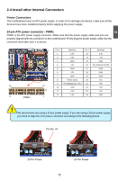
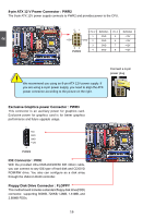
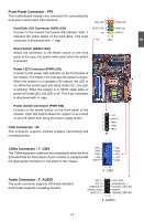
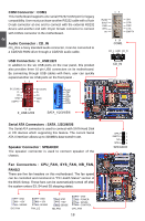
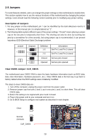
2 COM Connector : COM1 This motherboard supports one serial RS232 COM port for legacy compatibility. User must purchase another RS232 cable with a 9-pin D-sub connector at one end to connect with the external RS232 device and another end with 10-pin female connector to connect with COM1 connector in the motherboard. Audio Connector : CD_IN CD_IN is a Sony standard audio connector, it can be connected to a CD/DVD-ROM drive through a CD/DVD audio cable. RLSD SOUT GND RTS RI 12 SIN DTR DSR CTS EMPTY 9 10 COM1 CD_L GND CD_R USB Connectors : F_USB1/2/3 In addition to the six USB ports on the rear panel, this product also provides three 10-pin USB connectors on its motherboard. By connecting through USB cables with them, user can quickly expand another six USB ports on the front panel . 12 5V_DUAL DD+ GND EMPTY 5V_DUAL DD+ GND NC 1 GND TX+ TXGND RXRX+ GND 9 10 F_USB 1/2/3 SATA_1/2/3/4/5/6 CD_IN Serial ATA Connectors : SATA_1/2/3/4/5/6 The Serial ATA connector is used to connect with SATA Hard Disk or CD devices which supporting this feature. The current Serial ATA II interface allows up to 300MB/s data transfer rate. Speaker Connector : SPEAKER The speaker connector is used to connect speaker of the chassis. Fan Connectors : CPU_FAN, SYS_FAN, NB_FAN, FAN1/2 There are five fan headers on this motherboard. The fan speed can be controlled and monitored in "PC Health Status" section of the BIOS Setup. These fans can be automatically turned off after the system enters S3, S4 and S5 sleeping states. GND +12V SENSE SYS FAN GND +12V SENSE FAN_1/2 GND +12V SENSE NB_FAN GND POWER SENSE CONTROL CPU_FAN 18 SPKJ 1 EMPTY 2 NC 3 SPKJ 4 SPEAKER
-
 1
1 -
2
-
3
-
4
-
5
-
6
-
7
-
8
-
9
-
10
-
11
-
12
-
13
-
14
-
15
-
16
-
17
-
18
-
19
-
 20
20 -
 21
21 -
 22
22 -
 23
23 -
 24
24 -
 25
25 -
 26
26 -
 27
27 -
 28
28 -
 29
29 -
 30
30 -
31
-
32
-
33
-
34
-
35
-
36
-
37
-
38
-
39
-
40
-
41
-
42
-
43
-
44
-
45
-
46
-
47
-
48
-
49
-
50
-
51
-
52
-
53
-
54
-
55
-
56
-
57
-
58
-
59
-
60
-
61
-
62
-
63
-
64
-
65
-
66
-
67
-
68
-
69
-
70
-
71
-
72
-
73
-
74
-
75
-
76
-
77
-
78
-
79
-
80
-
81
-
82
-
83
-
84
-
85
-
86
-
87
-
88
-
89
-
90
-
91
-
92
-
93
-
94
-
95
-
96
-
97
-
98
-
99
-
100
-
101
-
102
-
103
-
104
-
105
-
106
-
107
-
108
-
109
-
110
 |
 |
