Garmin GPSMAP 172C Owner's Manual - Page 102
Wiring and, Interfacing, sonar NMEA input with support for the DPT Depth - power cable
 |
UPC - 753759043537
View all Garmin GPSMAP 172C manuals
Add to My Manuals
Save this manual to your list of manuals |
Page 102 highlights
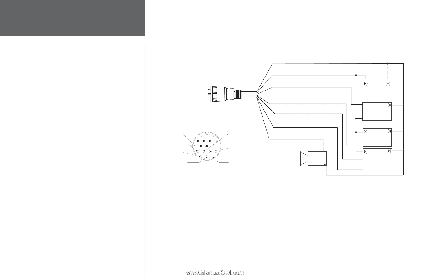
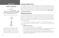
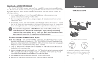
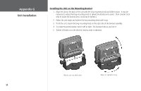
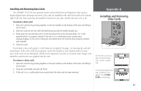
Appendix G Wiring and Interfacing You can download a copy of Garmin's proprietary communication protocol from the Help and Support section of our web site at www.garmin.com. Documentation concerning NMEA &RTCM formats and sentences are available for purchase from: National Marine Electronics Association (NMEA) Seven Riggs Avenue Severna Park, MD 21146 U.S.A. 410-975-9425 410-975-9450 FAX www.nmea.org Radio Technical Commission For Maritime Services (RTCM) 1800 Diagonal Road, Suite 600 Alexandria, VA 22314-2480 U.S.A. 703-684-4481 (Info Only) 703-836-4229 FAX www.rtcm.org 92 Connecting the Power/Data The power/data cable connects the GPSMAP 172/172C to a DC system and provides interface capabilities for connecting external devices. The color code in the diagram below indicates the appropriate harness connections. Replacement fuse is a AGC/3AG 2.0 Amp fuse. For wiring the GPSMAP to a GSD 20 Sonar Module, refer to the "GSD 20 Installation Guide" (190-00255-00). (red) 10-35 vDC Note: During a typical installation, only the Red and Black wires are used. The other wires do not have to be connected for normal operation of the unit. Replacement fuse: AGC/3AG - 2.0 Amp To Unit (black) Ground (Power and Data) (blue) NMEA OUT (Com 1 TX) (brown) NMEA IN (Com 1 RX) (white) RTCM/NMEA IN (Com 2 RX) (green) NMEA OUT (Com 2 TX) DC � Power Source RXD + Autopilot/ NMEA Device RXD - Pin 11 - Yellow (Alarm) Pin 15 - Red (DC Positive) Pin 18 - Black (Ground) Pin 14 - Green (TX COM 2) Pin 13 - White (RX COM 2) Pin 17 - Blue (TX COM 1) Interfacing Pin 16 - Brown (RX COM 1) (Cable End View) (yellow) Alarm Low Alarm Relay 100ma max coil current NMEA Device with Sonar Output TXD + GSD 20, TX+ Beacon Receiver or RX+ DSC VHF The following formats are supported for connection of external devices: Garmin proprietary GSD 20 Sonar Module and Differential GPS, NMEA 0183 version 3.01, RTCM SC-104 input (version 2.0). The following are the sentences for NMEA 0183, version 3.01 and later output: Approved sentences- GPBWC, GPRMC, GPGGA, GPGSA, GPGSV, GPGLL, GPBOD, GPRMB, GPRTE, GPVTG, GPWPL and GPXTE. Proprietary sentences- PGRME, PGRMM, PGRMZ, and PSLIB. The GPSMAP 172/172C also includes NMEA input with support for the WPL sentence, DSC, and sonar NMEA input with support for the DPT (Depth), MTW (Water Temp) and VHW (Water Speed & Heading) sentences. If connecting to COM2 for sonar NMEA input, the unit interface must be set to NMEA In/NMEA Out (see page 72). If connecting to COM1, the unit must be set to NMEA In/NMEA Out.
-
 1
1 -
2
-
3
-
4
-
5
-
6
-
7
-
8
-
9
-
10
-
11
-
12
-
13
-
14
-
15
-
16
-
17
-
18
-
19
-
20
-
21
-
22
-
23
-
24
-
25
-
26
-
27
-
28
-
29
-
30
-
31
-
32
-
33
-
34
-
35
-
36
-
37
-
38
-
39
-
40
-
41
-
42
-
43
-
44
-
45
-
46
-
47
-
48
-
49
-
50
-
51
-
52
-
53
-
54
-
55
-
56
-
57
-
58
-
59
-
60
-
61
-
62
-
63
-
64
-
65
-
66
-
67
-
68
-
69
-
70
-
71
-
72
-
73
-
74
-
75
-
76
-
77
-
78
-
79
-
80
-
81
-
82
-
83
-
84
-
85
-
86
-
87
-
88
-
89
-
90
-
91
-
92
-
93
-
94
-
95
-
96
-
 97
97 -
 98
98 -
 99
99 -
 100
100 -
 101
101 -
 102
102 -
 103
103 -
 104
104 -
 105
105 -
 106
106 -
 107
107 -
108
-
109
-
110
 |
 |