HP DL785 HP ProLiant DL785 G5 and G6 Servers - Maintenance and Service Guide, - Page 50
Midplane board, Remove all processor memory cells
 |
UPC - 883585262809
View all HP DL785 manuals
Add to My Manuals
Save this manual to your list of manuals |
Page 50 highlights
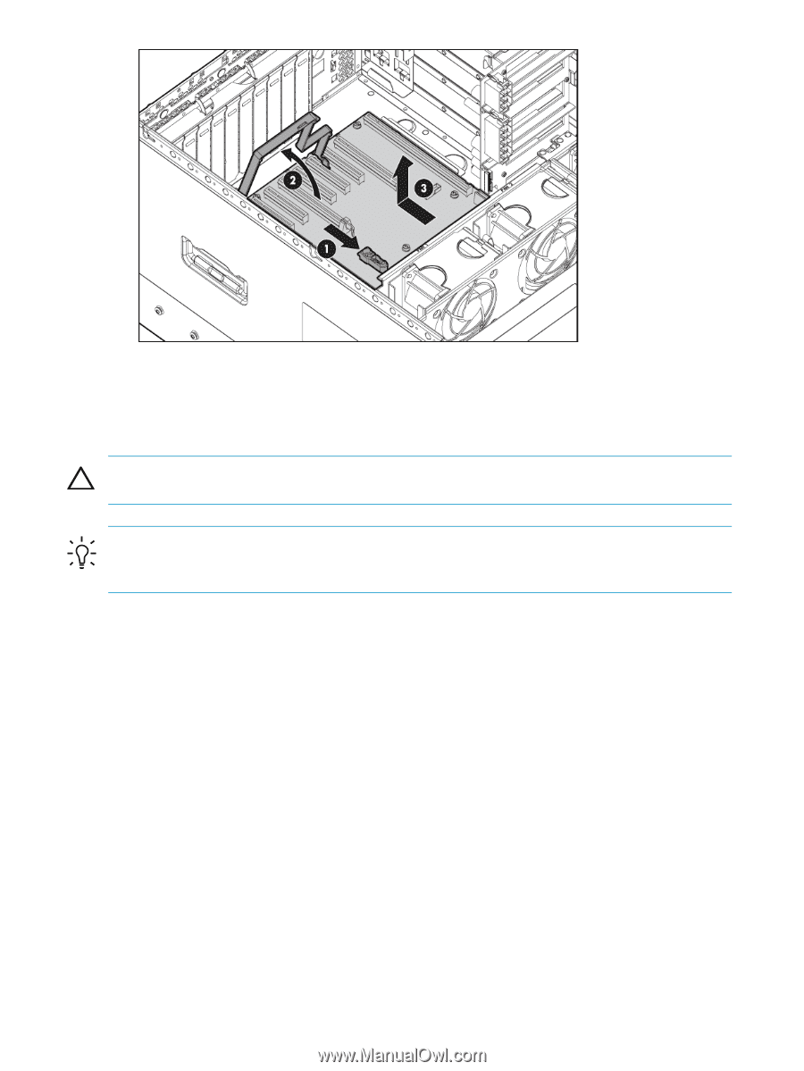
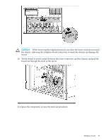
8. Pull the I/O backplane assembly out of the chassis. To replace the component, reverse the removal procedure. Midplane board CAUTION: Before starting this procedure, read the information about protecting against electrostatic discharge ("Preventing electrostatic discharge" (page 23)). TIP: HP recommends troubleshooting the system using port 85 codes before replacing the midplane board. See "Troubleshooting the system using port 85 codes" (page 57) for a list of codes and troubleshooting procedures. To remove the midplane board: 1. Power down the server ("Power down the server" (page 25)). 2. Remove the server from the rack ("Removing the server from the rack" (page 26)). 3. Remove the access panel ("Removing the access panel" (page 27)). 4. Remove all processor memory cells ("Processor memory cell" (page 29)). 5. Remove the cell filler ("Mezzanine filler" (page 29)). 6. Remove the I/O backplane assembly ("I/O backplane assembly" (page 49)). 7. Disconnect the cables from the midplane board. 8. Use a T-15 Torx screwdriver to remove the three screws securing the midplane board to the chassis. 9. Slide the midplane board to the right, over the anchoring pins. 50 Removal and replacement procedures
-
 1
1 -
2
-
3
-
4
-
5
-
6
-
7
-
8
-
9
-
10
-
11
-
12
-
13
-
14
-
15
-
16
-
17
-
18
-
19
-
20
-
21
-
22
-
23
-
24
-
25
-
26
-
27
-
28
-
29
-
30
-
31
-
32
-
33
-
34
-
35
-
36
-
37
-
38
-
39
-
40
-
41
-
42
-
43
-
44
-
 45
45 -
 46
46 -
 47
47 -
 48
48 -
 49
49 -
 50
50 -
 51
51 -
 52
52 -
 53
53 -
 54
54 -
 55
55 -
56
-
57
-
58
-
59
-
60
-
61
-
62
-
63
-
64
-
65
-
66
-
67
-
68
-
69
-
70
-
71
-
72
-
73
-
74
-
75
-
76
-
77
-
78
-
79
-
80
-
81
-
82
-
83
-
84
-
85
-
86
-
87
-
88
-
89
-
90
 |
 |