HP DL785 HP ProLiant DL785 G5 and G6 Servers - Maintenance and Service Guide, - Page 61
Component identification, Front panel components
 |
UPC - 883585262809
View all HP DL785 manuals
Add to My Manuals
Save this manual to your list of manuals |
Page 61 highlights
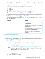
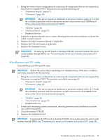
5 Component identification In this section • "Front panel components" (page 61) • "Front panel LEDs and buttons" (page 63) • "System Insight Display LEDs" (page 64) • "SAS and SATA hard drive LEDs" (page 66) • "SAS and SATA hard drive LED combinations" (page 66) • "Processor memory cell components" (page 67) • "Rear panel components" (page 68) • "Rear panel LEDs and buttons" (page 69) • "Power supply LED" (page 70) • "Internal components" (page 70) • "SPI board components" (page 72) • "System maintenance switch (SW6)" (page 72) • "System maintenance switch (SW1)" (page 74) • "Battery pack LEDs" (page 74) • "Fan locations" (page 75) Front panel components Item Description 1 USB connector 2 USB connector 3 Video connector 4 SID 5 DVD drive 6 Hard drive bay 1 right 7 Hard drive bay 2 right Front panel components 61
-
 1
1 -
2
-
3
-
4
-
5
-
6
-
7
-
8
-
9
-
10
-
11
-
12
-
13
-
14
-
15
-
16
-
17
-
18
-
19
-
20
-
21
-
22
-
23
-
24
-
25
-
26
-
27
-
28
-
29
-
30
-
31
-
32
-
33
-
34
-
35
-
36
-
37
-
38
-
39
-
40
-
41
-
42
-
43
-
44
-
45
-
46
-
47
-
48
-
49
-
50
-
51
-
52
-
53
-
54
-
55
-
 56
56 -
 57
57 -
 58
58 -
 59
59 -
 60
60 -
 61
61 -
 62
62 -
 63
63 -
 64
64 -
 65
65 -
 66
66 -
67
-
68
-
69
-
70
-
71
-
72
-
73
-
74
-
75
-
76
-
77
-
78
-
79
-
80
-
81
-
82
-
83
-
84
-
85
-
86
-
87
-
88
-
89
-
90
 |
 |