HP DL785 HP ProLiant DL785 G5 and G6 Servers - Maintenance and Service Guide, - Page 74
System maintenance switch (SW1), Battery pack LEDs, CAUTION - quickspecs
 |
UPC - 883585262809
View all HP DL785 manuals
Add to My Manuals
Save this manual to your list of manuals |
Page 74 highlights
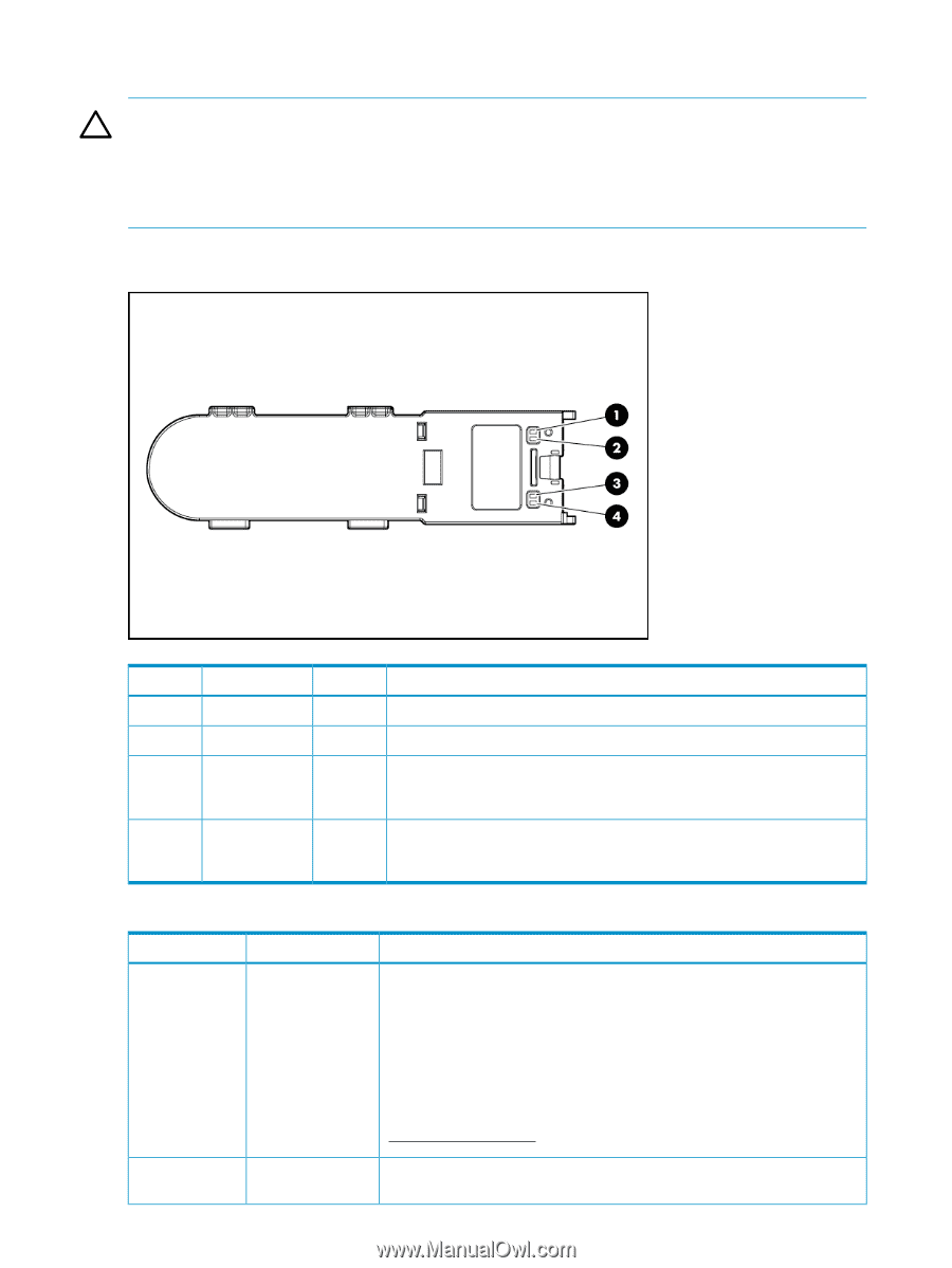
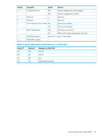
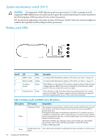
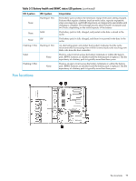
System maintenance switch (SW1) CAUTION: All supported AMD Opteron quad-core processors 3.1 GHz or greater and all supported AMD Opteron six-core processors require the system maintenance switch, located on the I/O backplane, (SW1) position 5 to be in the On position. HP recommends updating to the latest version of firmware. Earlier firmware versions might not validate the required switch setting for these processors. Battery pack LEDs Item ID 1 2 3 4 LED Color BBWC status Green Battery health Amber Auxiliary power Green System power Green Description To interpret the illumination patters of this LED, see Table 5-2 (page 74) To interpret the illumination patters of this LED, see Table 5-2 (page 74) This LED glows solid when 3.3 V auxiliary voltage is detected. The auxiliary voltage preserves BBWC data and is available any time that the system power cords are connected to a power supply. This LED glows solid when the system is powered up and 12 V system power is available. This power supply maintains the battery charge and provides supplementary power to the cache microcontroller. Table 5-2 Battery health and BBWC status LED patterns LED 3 pattern None LED 4 pattern Flashing (1/2 Hz) Interpretation The system is powered down, and the cache contains data that has not yet been written to the drives. Restore system power as soon as possible to prevent data loss. Data preservation time is extended any time that 3.3 V auxiliary power is available, as indicated by LED 2. In the absence of auxiliary power, battery power alone preserves the data. A fullycharged battery can normally preserve data for at least two days. The battery lifetime also depends on the cache module size. For further information, refer to the controller QuickSpecs on the HP website (http://www.hp.com). None Double flash, then The cache microcontroller is waiting for the host controller to communicate. pause 74 Component identification
-
 1
1 -
2
-
3
-
4
-
5
-
6
-
7
-
8
-
9
-
10
-
11
-
12
-
13
-
14
-
15
-
16
-
17
-
18
-
19
-
20
-
21
-
22
-
23
-
24
-
25
-
26
-
27
-
28
-
29
-
30
-
31
-
32
-
33
-
34
-
35
-
36
-
37
-
38
-
39
-
40
-
41
-
42
-
43
-
44
-
45
-
46
-
47
-
48
-
49
-
50
-
51
-
52
-
53
-
54
-
55
-
56
-
57
-
58
-
59
-
60
-
61
-
62
-
63
-
64
-
65
-
66
-
67
-
68
-
 69
69 -
 70
70 -
 71
71 -
 72
72 -
 73
73 -
 74
74 -
 75
75 -
 76
76 -
 77
77 -
 78
78 -
 79
79 -
80
-
81
-
82
-
83
-
84
-
85
-
86
-
87
-
88
-
89
-
90
 |
 |