HP Indigo 10000 HD Writing Head Service Document - Page 46
values and calculate, wizard to print the job and then cancel the wizard.
 |
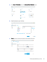
View all HP Indigo 10000 manuals
Add to My Manuals
Save this manual to your list of manuals |
Page 46 highlights
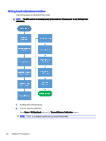
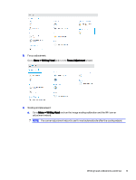
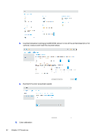
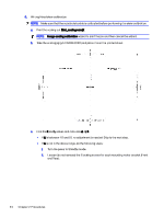
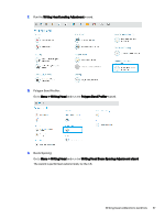
6. Writing Head skew calibration NOTE: Make sure that the substrate buckle is calibrated before performing the skew calibration. a. Print the scaling job. Eilat_scaling new.jlt NOTE: Image scaling calibration wizard to print the job and then cancel the wizard. b. Take the scaling jig (p/n CA098-00101) and place it over the printed sheet. c. Find the K and L values and calculate ∆ =L-K. ● If ∆ is between -0.1 and 0.1, no adjustment is needed. Skip to the next step. ● If ∆ is not in the above range, do the following steps: i. Turn the press to Standby mode. ii. Loosen (do not remove) the 2 locking screws for each mounting motor bracket (Front and Rear). 44 Chapter 2 Procedures
-
 1
1 -
2
-
3
-
4
-
5
-
6
-
7
-
8
-
9
-
10
-
11
-
12
-
13
-
14
-
15
-
16
-
17
-
18
-
19
-
20
-
21
-
22
-
23
-
24
-
25
-
26
-
27
-
28
-
29
-
30
-
31
-
32
-
33
-
34
-
35
-
36
-
37
-
38
-
39
-
40
-
 41
41 -
 42
42 -
 43
43 -
 44
44 -
 45
45 -
 46
46 -
 47
47 -
 48
48 -
 49
49 -
 50
50 -
 51
51 -
52
-
53
-
54
-
55
-
56
-
57
-
58
-
59
-
60
-
61
-
62
-
63
-
64
-
65
-
66
-
67
-
68
-
69
-
70
-
71
-
72
-
73
-
74
-
75
-
76
-
77
-
78
-
79
-
80
-
81
-
82
-
83
-
84
-
85
-
86
-
87
-
88
-
89
-
90
-
91
-
92
-
93
-
94
-
95
-
96
-
97
-
98
-
99
-
100
-
101
-
102
-
103
-
104
-
105
 |
 |

6.
Writing Head skew calibration
NOTE:
Make sure that the substrate buckle is calibrated before performing the skew calibration.
a.
Print the scaling job.
Eilat_scaling new.jlt
NOTE:
Image scaling calibration
wizard to print the job and then cancel the wizard.
b.
Take the scaling jig (p/n CA098-00101) and place it over the printed sheet.
c.
Find the
K
and
L
values and calculate
∆
=
L
-
K
.
●
If
∆
is between -0.1 and 0.1, no adjustment is needed. Skip to the next step.
●
If
∆
is not in the above range, do the following steps:
i.
Turn the press to Standby mode.
ii.
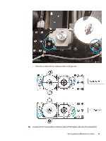
Loosen (do not remove) the 2 locking screws for each mounting motor bracket (Front
and Rear).
44
Chapter 2
Procedures