HP LaserJet Pro CP1025 Service Manual - Page 32
Pickup roller, Rotate the pickup roller to the service position, Before proceeding
 |
View all HP LaserJet Pro CP1025 manuals
Add to My Manuals
Save this manual to your list of manuals |
Page 32 highlights
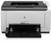
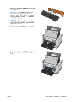
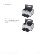
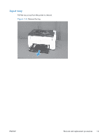
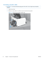
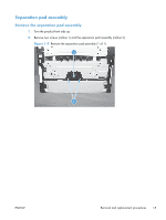
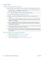
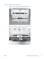
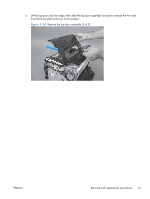
Pickup roller Rotate the pickup roller to the service position To gain access to the roller locking tabs you must rotate the roller to the correct position for removal. 1. When the product is in the Ready state, press and hold the Auto-On/Auto-Off (power) button for about seven seconds or until the Ready light turns off. TIP: Optionally, unplug the power cord, and then plug the cord back in. 2. Make sure that one sheet of paper is loaded in the input tray. NOTE: If more than one sheet of paper is loaded in the tray, this procedure will not be successful. 3. Press and release the Auto-On/Auto-Off (power) button and within two seconds press and hold down the cyan cartridge button. Hold the cyan button down for about five seconds, or until the initialization process begins. NOTE: Immediately after the Auto-On/Auto-Off (power) button is pressed, all of the control panel lights illuminate briefly (for about two seconds). You must press the cyan cartridge button while the lights are illuminated. 4. When the product finishes initializing, the roller rotates into the removal position. Turn the product off. Unplug the product before removing any components. NOTE: When the roller is in the removal position, the sheet of paper will have been pulled into the paper path by about 12 mm (.5 in). This is visual confirmation that the roller has rotated to the removal position. Before proceeding, remove the following components: ● Right cover assembly. See Right cover assembly on page 18. ● Left cover assembly. See Left cover assembly on page 19. ● Separation pad assembly. See Separation pad assembly on page 15. 16 Chapter 1 Removal and replacement ENWW
-
 1
1 -
2
-
3
-
4
-
5
-
6
-
7
-
8
-
9
-
10
-
11
-
12
-
13
-
14
-
15
-
16
-
17
-
18
-
19
-
20
-
21
-
22
-
23
-
24
-
25
-
26
-
 27
27 -
 28
28 -
 29
29 -
 30
30 -
 31
31 -
 32
32 -
 33
33 -
 34
34 -
 35
35 -
 36
36 -
 37
37 -
38
-
39
-
40
-
41
-
42
-
43
-
44
-
45
-
46
-
47
-
48
-
49
-
50
-
51
-
52
-
53
-
54
-
55
-
56
-
57
-
58
-
59
-
60
-
61
-
62
-
63
-
64
-
65
-
66
-
67
-
68
-
69
-
70
-
71
-
72
-
73
-
74
-
75
-
76
-
77
-
78
-
79
-
80
-
81
-
82
-
83
-
84
-
85
-
86
-
87
-
88
-
89
-
90
-
91
-
92
-
93
-
94
-
95
-
96
-
97
-
98
-
99
-
100
-
101
-
102
-
103
-
104
-
105
-
106
-
107
-
108
-
109
-
110
-
111
-
112
-
113
-
114
-
115
-
116
-
117
-
118
-
119
-
120
-
121
-
122
-
123
-
124
-
125
-
126
-
127
-
128
-
129
-
130
-
131
-
132
-
133
-
134
-
135
-
136
-
137
-
138
-
139
-
140
-
141
-
142
-
143
-
144
-
145
-
146
-
147
-
148
-
149
-
150
-
151
-
152
-
153
-
154
-
155
-
156
-
157
-
158
-
159
-
160
-
161
-
162
-
163
-
164
-
165
-
166
 |
 |