HP LaserJet Pro CP1025 Service Manual - Page 41
Control panel, Remove the control panel, CAUTION, Before proceeding, remove the following components
 |
View all HP LaserJet Pro CP1025 manuals
Add to My Manuals
Save this manual to your list of manuals |
Page 41 highlights
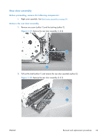
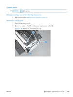
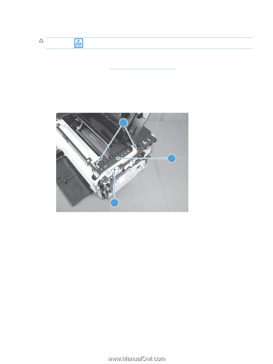
Control panel CAUTION: ESD sensitive. Before proceeding, remove the following components: ● Right cover assembly. See Right cover assembly on page 18. Remove the control panel 1. Open the top door assembly. 2. Remove two screws (callout 1) and disconnect one connector (callout 2). Figure 1-20 Remove the control panel (1 of 2) 1 4 2 ENWW Removal and replacement procedures 25
-
 1
1 -
2
-
3
-
4
-
5
-
6
-
7
-
8
-
9
-
10
-
11
-
12
-
13
-
14
-
15
-
16
-
17
-
18
-
19
-
20
-
21
-
22
-
23
-
24
-
25
-
26
-
27
-
28
-
29
-
30
-
31
-
32
-
33
-
34
-
35
-
 36
36 -
 37
37 -
 38
38 -
 39
39 -
 40
40 -
 41
41 -
 42
42 -
 43
43 -
 44
44 -
 45
45 -
 46
46 -
47
-
48
-
49
-
50
-
51
-
52
-
53
-
54
-
55
-
56
-
57
-
58
-
59
-
60
-
61
-
62
-
63
-
64
-
65
-
66
-
67
-
68
-
69
-
70
-
71
-
72
-
73
-
74
-
75
-
76
-
77
-
78
-
79
-
80
-
81
-
82
-
83
-
84
-
85
-
86
-
87
-
88
-
89
-
90
-
91
-
92
-
93
-
94
-
95
-
96
-
97
-
98
-
99
-
100
-
101
-
102
-
103
-
104
-
105
-
106
-
107
-
108
-
109
-
110
-
111
-
112
-
113
-
114
-
115
-
116
-
117
-
118
-
119
-
120
-
121
-
122
-
123
-
124
-
125
-
126
-
127
-
128
-
129
-
130
-
131
-
132
-
133
-
134
-
135
-
136
-
137
-
138
-
139
-
140
-
141
-
142
-
143
-
144
-
145
-
146
-
147
-
148
-
149
-
150
-
151
-
152
-
153
-
154
-
155
-
156
-
157
-
158
-
159
-
160
-
161
-
162
-
163
-
164
-
165
-
166
 |
 |
Control panel
CAUTION:
ESD sensitive.
Before proceeding, remove the following components:
●
Right cover assembly. See
Right cover assembly
on page
18
.
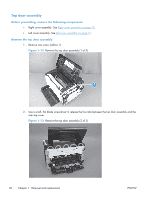
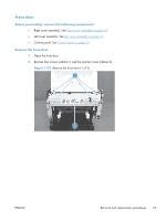
Remove the control panel
1.
Open the top door assembly.
2.
Remove two screws (callout 1) and disconnect one connector (callout 2).
Figure 1-20
Remove the control panel (1 of 2)
1
4
2
ENWW
Removal and replacement procedures
25