HP LaserJet Pro CP1025 Service Manual - Page 62
Engine controller assembly, CAUTION, Before proceeding, remove the following components,
 |
View all HP LaserJet Pro CP1025 manuals
Add to My Manuals
Save this manual to your list of manuals |
Page 62 highlights
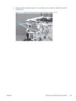
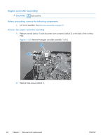
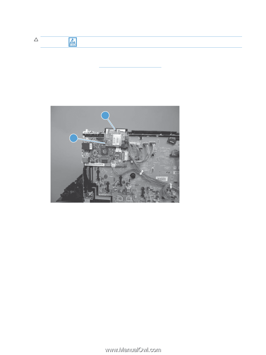
Engine controller assembly CAUTION: ESD sensitive. Before proceeding, remove the following components: ● Left cover assembly. See Left cover assembly on page 19. Remove the engine controller assembly 1. Release one tab (callout 1) and disconnect one connector (callout 2) on the back of the wireless PCA. Figure 1-52 Remove the engine controller assembly (1 of 5) 1 2 2. Remove three screws (callout 1). 46 Chapter 1 Removal and replacement ENWW
-
 1
1 -
2
-
3
-
4
-
5
-
6
-
7
-
8
-
9
-
10
-
11
-
12
-
13
-
14
-
15
-
16
-
17
-
18
-
19
-
20
-
21
-
22
-
23
-
24
-
25
-
26
-
27
-
28
-
29
-
30
-
31
-
32
-
33
-
34
-
35
-
36
-
37
-
38
-
39
-
40
-
41
-
42
-
43
-
44
-
45
-
46
-
47
-
48
-
49
-
50
-
51
-
52
-
53
-
54
-
55
-
56
-
 57
57 -
 58
58 -
 59
59 -
 60
60 -
 61
61 -
 62
62 -
 63
63 -
 64
64 -
 65
65 -
 66
66 -
 67
67 -
68
-
69
-
70
-
71
-
72
-
73
-
74
-
75
-
76
-
77
-
78
-
79
-
80
-
81
-
82
-
83
-
84
-
85
-
86
-
87
-
88
-
89
-
90
-
91
-
92
-
93
-
94
-
95
-
96
-
97
-
98
-
99
-
100
-
101
-
102
-
103
-
104
-
105
-
106
-
107
-
108
-
109
-
110
-
111
-
112
-
113
-
114
-
115
-
116
-
117
-
118
-
119
-
120
-
121
-
122
-
123
-
124
-
125
-
126
-
127
-
128
-
129
-
130
-
131
-
132
-
133
-
134
-
135
-
136
-
137
-
138
-
139
-
140
-
141
-
142
-
143
-
144
-
145
-
146
-
147
-
148
-
149
-
150
-
151
-
152
-
153
-
154
-
155
-
156
-
157
-
158
-
159
-
160
-
161
-
162
-
163
-
164
-
165
-
166
 |
 |
Engine controller assembly
CAUTION:
ESD sensitive.
Before proceeding, remove the following components:
●
Left cover assembly. See
Left cover assembly
on page
19
.
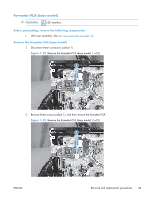
Remove the engine controller assembly
1.
Release one tab (callout 1) and disconnect one connector (callout 2) on the back of the wireless
PCA.
Figure 1-52
Remove the engine controller assembly (1 of 5)
1
2
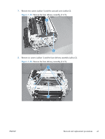
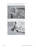
2.
Remove three screws (callout 1).
46
Chapter 1
Removal and replacement
ENWW