HP LaserJet Pro CP1025 Service Manual - Page 35
Left cover assembly, Remove the left cover assembly,
 |
View all HP LaserJet Pro CP1025 manuals
Add to My Manuals
Save this manual to your list of manuals |
Page 35 highlights
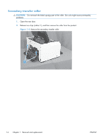
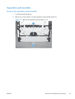
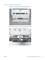
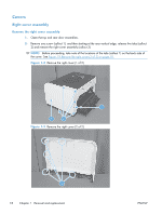
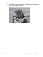
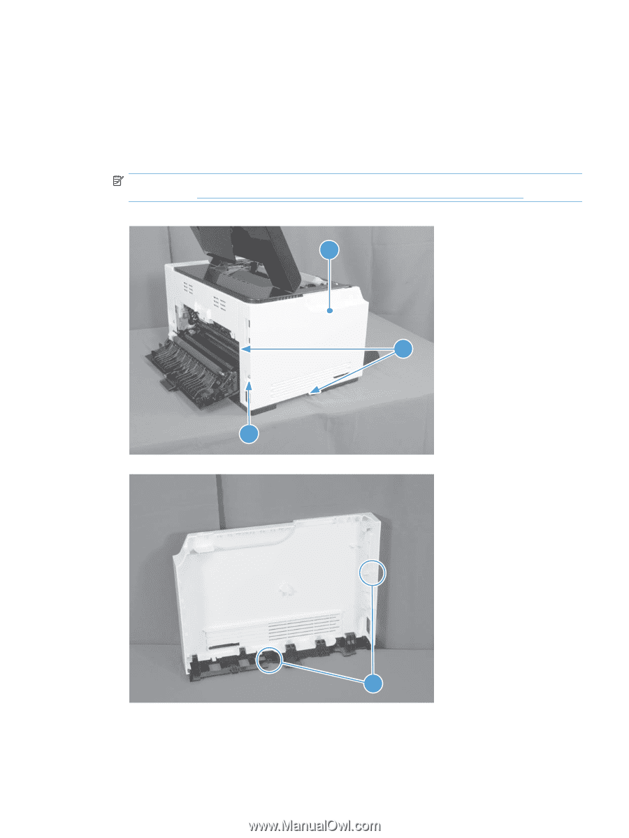
Left cover assembly Remove the left cover assembly 1. Open the top door. 2. Remove one screw (callout 1), and then starting at the rear vertical edge, release two tabs (callout 2) and remove the left cover assembly (callout 3). NOTE: Before proceeding, take note of the locations of the tabs (callout 2) on the back side of the cover. See Figure 1-11 Remove the left cover, duplex product (2 of 2) on page 19. Figure 1-10 Remove the left cover (1 of 2) 3 2 1 Figure 1-11 Remove the left cover, duplex product (2 of 2) ENWW 2 Removal and replacement procedures 19
-
 1
1 -
2
-
3
-
4
-
5
-
6
-
7
-
8
-
9
-
10
-
11
-
12
-
13
-
14
-
15
-
16
-
17
-
18
-
19
-
20
-
21
-
22
-
23
-
24
-
25
-
26
-
27
-
28
-
29
-
 30
30 -
 31
31 -
 32
32 -
 33
33 -
 34
34 -
 35
35 -
 36
36 -
 37
37 -
 38
38 -
 39
39 -
 40
40 -
41
-
42
-
43
-
44
-
45
-
46
-
47
-
48
-
49
-
50
-
51
-
52
-
53
-
54
-
55
-
56
-
57
-
58
-
59
-
60
-
61
-
62
-
63
-
64
-
65
-
66
-
67
-
68
-
69
-
70
-
71
-
72
-
73
-
74
-
75
-
76
-
77
-
78
-
79
-
80
-
81
-
82
-
83
-
84
-
85
-
86
-
87
-
88
-
89
-
90
-
91
-
92
-
93
-
94
-
95
-
96
-
97
-
98
-
99
-
100
-
101
-
102
-
103
-
104
-
105
-
106
-
107
-
108
-
109
-
110
-
111
-
112
-
113
-
114
-
115
-
116
-
117
-
118
-
119
-
120
-
121
-
122
-
123
-
124
-
125
-
126
-
127
-
128
-
129
-
130
-
131
-
132
-
133
-
134
-
135
-
136
-
137
-
138
-
139
-
140
-
141
-
142
-
143
-
144
-
145
-
146
-
147
-
148
-
149
-
150
-
151
-
152
-
153
-
154
-
155
-
156
-
157
-
158
-
159
-
160
-
161
-
162
-
163
-
164
-
165
-
166
 |
 |
Left cover assembly
Remove the left cover assembly
1.
Open the top door.
2.
Remove one screw (callout 1), and then starting at the rear vertical edge, release two tabs (callout
2) and remove the left cover assembly (callout 3).
NOTE:
Before proceeding, take note of the locations of the tabs (callout 2) on the back side of
the cover. See
Figure
1
-
11
Remove the left cover, duplex product (2 of 2)
on page
19
.
Figure 1-10
Remove the left cover (1 of 2)
3
1
2
Figure 1-11
Remove the left cover, duplex product (2 of 2)
2
ENWW
Removal and replacement procedures
19