HP Scanjet 1000 User Guide - Page 11
Setting up the monitor, Installing the monitor stand, Mounting the monitor
 |
View all HP Scanjet 1000 manuals
Add to My Manuals
Save this manual to your list of manuals |
Page 11 highlights
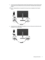
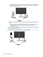
NOTE: To view an OSD menu simulator, visit the HP Customer Self Repair Services Media Library at http://www.hp.com/go/sml. Setting up the monitor Installing the monitor stand IMPORTANT: To prevent damage to the monitor, do not touch the surface of the LCD panel. Pressure on the panel may cause nonuniformity of color or disorientation of the liquid crystals. If this occurs, the screen will not recover to its normal condition. 1. Position the monitor head facedown on a flat surface covered by protective sheet made of foam or a clean, dry cloth. 2. Slide the top of the mounting plate on the stand under the upper lip of the recess in the back of the monitor head (1). 3. Lower the bottom of the stand's mounting plate into the recess until it snaps into place (2). The latch on the bottom of the mounting plate pops up when the stand is locked in place. Mounting the monitor The monitor head can be attached to a wall, swing arm, or other mounting fixture. NOTE: This apparatus is intended to be supported by a UL- or CSA-Listed wall-mount bracket. IMPORTANT: This monitor supports the VESA® industry-standard 100 mm mounting holes. To attach a third-party mounting solution to the monitor head, use four 4 mm, 0.7 pitch, 10 mm-long screws. Longer screws must not be used because they may damage the monitor. It is important to verify that the manufacturer's mounting solution is compliant with the VESA standard and is rated to support the weight of the monitor head. For best performance, it is important to use the power and video cables provided with the monitor. Setting up the monitor 5
-
 1
1 -
2
-
3
-
4
-
5
-
 6
6 -
 7
7 -
 8
8 -
 9
9 -
 10
10 -
 11
11 -
 12
12 -
 13
13 -
 14
14 -
 15
15 -
 16
16 -
17
-
18
-
19
-
20
-
21
-
22
-
23
-
24
-
25
-
26
-
27
-
28
-
29
-
30
-
31
-
32
-
33
-
34
-
35
-
36
-
37
-
38
-
39
-
40
-
41
-
42
-
43
-
44
-
45
-
46
-
47
 |
 |
