HP Scanjet 5000 User Guide
HP Scanjet 5000 Manual
 |
View all HP Scanjet 5000 manuals
Add to My Manuals
Save this manual to your list of manuals |
HP Scanjet 5000 manual content summary:
- HP Scanjet 5000 | User Guide - Page 1
HP DL380z Gen9 Virtual Workstation User Guide - HP Scanjet 5000 | User Guide - Page 2
to change without notice. The only warranties for HP products and services are set forth in the express warranty statements accompanying such products and services. Nothing herein should be construed as constituting an additional warranty. HP shall not be liable for technical or editorial errors - HP Scanjet 5000 | User Guide - Page 3
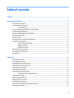
and buttons ...3 Power fault LEDs ...4 Accessing the optional HP Systems Insight Display 4 Systems Insight Display LEDs ...5 Systems Non-hot-plug PCI riser board slot definitions ...9 System board components ...10 System maintenance switch ...11 NMI functionality ...12 DIMM slot locations ...12 - HP Scanjet 5000 | User Guide - Page 4
4 Setup ...26 Optional installation services ...26 Optimum environment ...27 Space and airflow requirements ...27 QuickSpecs ...34 Introduction ...34 Processor and fan option ...34 Memory options ...40 HP SmartMemory ...40 Memory subsystem architecture ...41 Single-, dual-, and quad-rank DIMMs - HP Scanjet 5000 | User Guide - Page 5
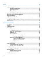
HP Insight Remote Support central connect 100 HP Insight Online direct connect 100 HP Insight Online ...100 Intelligent Provisioning ...101 HP Insight Diagnostics ...101 HP Insight Diagnostics survey functionality 101 Erase Utility ...102 Scripting Toolkit for Windows and Linux ...102 HP Service - HP Scanjet 5000 | User Guide - Page 6
...108 Drivers ...108 Software and firmware ...108 Version control ...108 HP operating systems and virtualization software support for ProLiant servers 109 HP Technology Service Portfolio ...109 Change control and proactive notification 109 8 Troubleshooting ...110 Troubleshooting resources - HP Scanjet 5000 | User Guide - Page 7
800W Flex Slot Platinum Hot-plug Power Supply 117 HP 1400W Flex Slot Platinum Plus Hot-plug Power Supply 118 13 Support and other resources ...119 Before you contact HP ...119 HP contact information ...119 Customer Self Repair ...120 14 Acronyms and abbreviations ...121 15 Documentation feedback - HP Scanjet 5000 | User Guide - Page 8
viii - HP Scanjet 5000 | User Guide - Page 9
1 Abstract This document is for the person who installs, administers, and troubleshoots servers and storage systems. HP assumes you are qualified in the servicing of computer equipment and trained in recognizing hazards in products with hazardous energy levels. This virtual workstations product is - HP Scanjet 5000 | User Guide - Page 10
2 Component identification Front panel components Item 1 2 3 4 5 Description Bay 1 (optional drives or optical drive, video, USB) Bay 2 (optional drives) Fixed drive bays Front USB 3.0 connector Serial label pull tab 2 Chapter 2 Component identification - HP Scanjet 5000 | User Guide - Page 11
blue: ● (1 Hz/cycle per sec) = Remote management or firmware upgrade in progress ● 4 Hz/cycle per sec = iLO manual reboot sequence initiated ● 8 Hz/cycle per sec = iLO manual reboot sequence in progress Off = Deactivated *When all four LEDs described in this table flash simultaneously, a power - HP Scanjet 5000 | User Guide - Page 12
System board PCIe slots 7 flashes Power backplane or storage backplane 8 flashes Power supply 9 flashes Accessing the optional HP Systems Insight Display To access a pop-out HP Systems Insight Display on models with this option installed: 1. Press and release the panel. 2. After the display - HP Scanjet 5000 | User Guide - Page 13
Systems Insight Display LEDs The HP Systems Insight Display LEDs represent the system board layout. The display enables diagnosis with the access panel installed. Item 1 Description NIC link/activity 2 Over temp 3 - HP Scanjet 5000 | User Guide - Page 14
in socket X is in a pre-failure condition. One or more DIMMs have failed. DIMM in slot X is in a pre-failure condition. The Health Driver has detected a cautionary temperature level. The server has detected a hardware critical temperature level. The PCI riser cage is not seated properly. One fan has - HP Scanjet 5000 | User Guide - Page 15
one DIMM slot LED is illuminated, further troubleshooting is required. Test each bank of DIMMs by removing all other DIMMs. Isolate the failed DIMM by replacing each DIMM in a bank with a known working DIMM. Rear panel components Item 1 2 3 4 5 6 7 8 9 10 11 12 13 Description PCIe slots 1-3 (top - HP Scanjet 5000 | User Guide - Page 16
Rear panel LEDs Item 1 2 3 4 5 Description UID LED NIC link LED NIC activity LED Power supply 2 LED Power supply 1 LED Status Off = Deactivated Solid blue = Activated Flashing blue = System being managed remotely Off = No network link Green = Network link Off = No network activity Solid green = - HP Scanjet 5000 | User Guide - Page 17
the riser cages listed in the table above in either the primary or secondary riser connectors determines the form factor of the PCI expansion boards supported by those riser cages. ● FL/FH denotes full-length, full-height. HL/FH denotes half-length, full-height. Non-hot-plug PCI riser board slot - HP Scanjet 5000 | User Guide - Page 18
SATA port 2 Backplane presence detect connector Optical/SATA port 5 SATA port 4 Front power/USB 3.0 connector Drive backplane power connector HP Smart Storage Battery connector Optional Location Discovery Services connector Micro SD card slot Dual internal USB 3.0 connector Smart Array/HBA connector - HP Scanjet 5000 | User Guide - Page 19
properly configure the server or data loss could occur. IMPORTANT: Before using the S7 switch to change to Legacy BIOS Boot Mode, be sure the HP Dynamic Smart Array B140i Controller is disabled. Do not use the B140i controller when the server is in Legacy BIOS Boot Mode. System board components - HP Scanjet 5000 | User Guide - Page 20
drivers, and applications. Many crashes freeze a system, and the only available action for administrators is to cycle the system power. Resetting the system erases any information that could support problem , go to the HP website http://www.hp.com/support/NMI. DIMM slot locations DIMM slots are numbered - HP Scanjet 5000 | User Guide - Page 21
SAS and SATA device numbers ● SFF 8-device bay numbering Hot-plug drive LED definitions Item 1 2 3 4 LED Locate Activity ring Do not remove Drive status Status Solid blue Flashing blue Rotating green Off Solid white Off Solid green Flashing green Flashing amber/green Flashing amber Solid amber - HP Scanjet 5000 | User Guide - Page 22
optimal number of fans installed. Although the server might boot, HP does not recommend operating the server without the required fans installed required number of fans in a single-processor configuration is not a supported configuration. For a dual-processor configuration, six fans are required for - HP Scanjet 5000 | User Guide - Page 23
For more information, go to the HP website http://www.hp.com/go/proliant/ASHRAE. The server supports variable fan speeds. The fans operate at minimum speed until a temperature change requires a fan speed increase to cool the server. The server shuts down during - HP Scanjet 5000 | User Guide - Page 24
and the OS. If an application stops responding, you can use this method to force a shutdown. ● Use a virtual power button selection through HP iLO. This method initiates a controlled remote shutdown of applications and the OS before the server enters standby mode. Before proceeding, verify the - HP Scanjet 5000 | User Guide - Page 25
sliding the server into the rack. The sliding rails could pinch your fingers. Removing the server from the rack To remove the server from an HP, Compaq branded, telco, or third-party rack: 1. Power down the server (see Powering down the server on page 16). 2. Extend the server from the rack - HP Scanjet 5000 | User Guide - Page 26
Removing the access panel WARNING! To reduce the risk of personal injury from hot surfaces, allow the drives and the internal system components to cool before touching them. CAUTION: Do not operate the server for long periods with the access panel open or removed. Operating the server in this manner - HP Scanjet 5000 | User Guide - Page 27
Accessing the product rear panel Opening the cable management arm To access the server rear panel: 1. Release the cable management arm. 2. Open the cable management arm. Note that the cable management arm can be right-mounted or leftmounted. Accessing the product rear panel 19 - HP Scanjet 5000 | User Guide - Page 28
Removing the fan cage To remove the component: 1. Power down the server (see Powering down the server on page 16). 2. Remove all power: a. Disconnect each power cord from the power source. b. Disconnect each power cord from the server. 3. Extend the server from the rack, (see Extending the server - HP Scanjet 5000 | User Guide - Page 29
Removing the hot-plug fan To remove the component: 1. Power down the server (see Powering down the server on page 16). 2. Remove all power: a. Disconnect each power cord from the power source. b. Disconnect each power cord from the server. 3. Extend the server from the rack (see Extending the server - HP Scanjet 5000 | User Guide - Page 30
Removing the PCI riser cage CAUTION: To prevent damage to the server or expansion boards, power down the server and remove all AC power cords before removing or installing the PCI riser cage. 1. Power down the server (see Powering down the server on page 16). 2. Remove all power: a. Disconnect each - HP Scanjet 5000 | User Guide - Page 31
(see Installing the server into the rack on page 30). 8. Connect each power cord to the server. 9. Connect each power cord to the power source. 10. Power up the server (see Powering up the server on page 16). Installing the PCI riser cage 23 - HP Scanjet 5000 | User Guide - Page 32
access panel (see Installing the access panel on page 18). 9. Install the server into the rack (Installing the server into the rack on page 30). 10. Connect each power cord to the server. 11. Connect each power cord to the power source. 12. Power up the server (see Powering up the - HP Scanjet 5000 | User Guide - Page 33
CAUTION: For proper cooling, do not operate the server without the access panel, baffles, expansion slot covers, or blanks installed. If the server supports hot-plug components, minimize the amount of time the access panel is open. To remove the component: 1. Power down the server (see Powering - HP Scanjet 5000 | User Guide - Page 34
KVM ● Integrated hardware and software support ◦ Critical Service ◦ Proactive 24 ◦ Support Plus ◦ Support Plus 24 ● Startup and implementation services for both hardware and software For more information on HP Care Pack Services, go to the HP website http://www.hp.com/services/carepack. 26 Chapter - HP Scanjet 5000 | User Guide - Page 35
in this section. Space and airflow requirements To allow for servicing and adequate airflow, observe the following space and airflow requirements (2.75 in). IMPORTANT: The HP ProLiant DL380p Gen8 Server cable management arm is not supported on Compaq branded 7000 series racks. Optimum environment - HP Scanjet 5000 | User Guide - Page 36
listed or certified grounding-type devices. Because of the high ground-leakage currents associated with multiple servers connected to the same power source, HP recommends the use of a PDU that is either permanently wired to the building's branch circuit or includes a nondetachable cord that is wired - HP Scanjet 5000 | User Guide - Page 37
with the rack or the server. The contents of the server shipping carton include: ● Server ● Power cord ● Hardware documentation, Documentation CD, and software products ● Rack-mounting hardware and documentation In addition to the supplied items, you might need: ● Operating system or application - HP Scanjet 5000 | User Guide - Page 38
from the bottom to the top. 1. Install the server and cable management arm into the rack. For more information, see the installation instructions that ship with the 2U Quick Deploy Rail System. 2. Connect peripheral devices to the server. For information on identifying connectors, see Rear panel - HP Scanjet 5000 | User Guide - Page 39
media. Everything needed to manage and install the system software and firmware is preloaded on the server. To operate properly, the server must have a supported operating system. For the latest information on operating system support, go to the DL380z Gen9 Virtual Workstation QuickSpecs http - HP Scanjet 5000 | User Guide - Page 40
media-to install Window or Linux, use the installation media provided with your product. Use the installation instructions provided on the DVD. For additional system software and firmware updates, go to the HP website http://www.hp.com/support/ DL380zGen9/download. Software and firmware must - HP Scanjet 5000 | User Guide - Page 41
software, press F10 to access Intelligent Provisioning. For more information on automatic configuration, go to the HP UEFI System Utilities User Guide on the HP website http://www.hp.com/go/ProLiantUEFI/docs. Registering the server To experience quicker service and more efficient support, register - HP Scanjet 5000 | User Guide - Page 42
HP website http://www8.hp.com/h20195/v2/GetDocument.aspx? docname=c04484636. Introduction If more than one option is being installed, read the installation instructions electrostatic discharge. Processor and fan option The server supports single-processor and dual-processor operations. CAUTION: To - HP Scanjet 5000 | User Guide - Page 43
7. Open each of the processor locking levers in the order indicated in the following illustration, and then open the processor retaining bracket. 8. Remove the clear processor socket cover. Retain the processor socket cover for future use. CAUTION: THE PINS ON THE SYSTEM BOARD ARE VERY FRAGILE AND - HP Scanjet 5000 | User Guide - Page 44
fully seated in the processor retaining bracket by visually inspecting the processor installation guides on either side of the processor. THE PINS ON THE SYSTEM BOARD ARE VERY FRAGILE AND EASILY DAMAGED. 10. Close the processor retaining bracket. When the processor is installed properly inside the - HP Scanjet 5000 | User Guide - Page 45
11. Press and hold the processor retaining bracket in place, and then close each processor locking lever. Press only in the area indicated on the processor retaining bracket. CAUTION: Close and hold down the processor cover socket while closing the processor locking levers. The levers should close - HP Scanjet 5000 | User Guide - Page 46
14. Remove the fan blanks from locations 1 and 2. For fan location and numbering information, see Hotplug fans on page 14 or the label attached to the chassis next to the fans. 38 Chapter 5 Hardware options installation - HP Scanjet 5000 | User Guide - Page 47
15. Install the fans into locations 1 and 2. 16. Install the air baffle. 17. Install the access panel, see Installing the access panel on page 18. 18. Install the server into the rack. 19. Connect each power cord to the server. 20. Connect each power cord to the power source. 21. Press the Power On/ - HP Scanjet 5000 | User Guide - Page 48
and verifies whether installed memory has passed HP qualification and test processes. Qualified memory is performance-tuned for HP ProLiant and BladeSystem servers and provides future enhanced support through HP Active Health and manageability software. 40 Chapter 5 Hardware options installation - HP Scanjet 5000 | User Guide - Page 49
in this server is divided into channels. Each processor supports four channels, and each channel supports three DIMM slots, as shown in the following table. Channel 1 2 3 4 Population order A E I B F J C G K D H L Slot number 12 11 10 9 8 7 1 2 3 4 5 6 For the location of the slot numbers, see - HP Scanjet 5000 | User Guide - Page 50
features, specifications, options, configurations, and compatibility, go to the product QuickSpecs on the HP website http://www.hp.com/go/qs. Memory configurations To optimize server availability, the server supports the following AMP modes: ● Advanced ECC-provides up to 4-bit error correction and - HP Scanjet 5000 | User Guide - Page 51
RBSU). If the requested AMP mode is not supported by the installed DIMM configuration, the server boots in Advanced ECC mode. For more information, go to the HP UEFI System Utilities User Guide for HP ProLiant Gen9 Servers on the HP website http://www.hp.com/go/uefi/docs. Table 5-1 Maximum capacity - HP Scanjet 5000 | User Guide - Page 52
For DIMM spare replacement, install the DIMMs per slot number as instructed by the system software. For more information about server memory, go to the HP website http://www.hp.com/go/memory. DIMM speeds are supported as indicated in the following table. Populated slots (per channel) 1 2 2 3 Rank - HP Scanjet 5000 | User Guide - Page 53
Configuration (RBSU) in the UEFI System Utilities to configure supported AMP modes. Installing a DIMM The server supports up to 24 DIMMs. To install a DIMM: 1. panel (see Installing the access panel on page 18). 10. Install the server into the rack (see Installing the server into the rack on page - HP Scanjet 5000 | User Guide - Page 54
Use the BIOS/Platform Configuration (RBSU) in the UEFI System Utilities to configure the memory mode. For more information about LEDs and troubleshooting failed DIMMs, see Systems Insight Display LED combinations on page 5. Hot-plug hard drive options When adding hard drives to the server, observe - HP Scanjet 5000 | User Guide - Page 55
Installing a hot-plug SAS or SATA hard drive To install the component: 1. Remove the drive blank. 2. Prepare the drive. 3. Install the drive. 4. Determine the status of the drive from the drive LED definitions (see Hot-plug drive LED definitions on page 13). Hot-plug hard drive options 47 - HP Scanjet 5000 | User Guide - Page 56
drive CAUTION: For proper cooling, do not operate the server without the access panel, baffles, expansion slot covers, or blanks installed. If the server supports hot-plug components, minimize the amount of time the access panel is open. 1. Determine the status of the drive from the hot-plug SAS - HP Scanjet 5000 | User Guide - Page 57
7. Remove the bay blank. 8. Route the USB/VGA cables through the opening, and then install the universal media bay. Universal media bay option 49 - HP Scanjet 5000 | User Guide - Page 58
9. Install the optional optical disk drive (optional). 10. Connect the cables: a. Connect the VGA cable to the optional VGA connector. Connect the USB cable to the front dual internal USB 3.0 connector. 50 Chapter 5 Hardware options installation - HP Scanjet 5000 | User Guide - Page 59
b. Connect the SATA optical drive cable to the front optical disk drive connector (optional). 11. Install the fan cage. 12. Install the air baffle. 13. Install the access panel (see Installing the access panel on page 18). 14. Slide the server into the rack. 15. Connect each power cord to the server - HP Scanjet 5000 | User Guide - Page 60
practices when routing power cords and other cables. A cable management arm is available to help with routing. To obtain a cable management arm, contact an HP authorized reseller. 6. Connect the power cord to the AC power source. 7. Be sure that the power supply LED is green (see Rear panel LEDs - HP Scanjet 5000 | User Guide - Page 61
. CAUTION: For proper cooling, do not operate the server without the access panel, baffles, expansion slot covers, or blanks installed. If the server supports hot-plug components, minimize the amount of time the access panel is open. To remove the component: 1. Power down the server (see Powering - HP Scanjet 5000 | User Guide - Page 62
● Optional primary PCI riser cage ● Secondary PCI riser cage To replace the component, reverse the removal procedure. 54 Chapter 5 Hardware options installation - HP Scanjet 5000 | User Guide - Page 63
board. See the documentation that ships with the expansion board. 9. Install the PCI riser cate (see Installing the PCI riser cage on page 23). 10. Install the access panel (see Installing the access panel on page 18). 11. Install the server into the rack (Installing the server into the rack - HP Scanjet 5000 | User Guide - Page 64
2-slot PCI riser cage option WARNING! To reduce the risk of personal injury, electric shock, or damage to the equipment, remove the power cord to remove power from the server. The front panel Power On/Standby button does not completely shut off system power. Portions of the power supply and some - HP Scanjet 5000 | User Guide - Page 65
2-slot PCI riser cage. 9. Connect any required internal or external cables to the expansion board. See the documentation that ships with the expansion board. 10. Install the access panel (see Installing the access panel on page 18). 11. Slide the server into the rack. 2-slot PCI riser cage option - HP Scanjet 5000 | User Guide - Page 66
12. Connect each power cord to the server. 13. Connect each power cord to the power source. 14. Power up the server (see Powering up the server on page 16). 3-slot PCI riser cage option WARNING! To reduce the risk of personal injury, electric shock, or damage to the equipment, remove the power cord - HP Scanjet 5000 | User Guide - Page 67
board into the PCI riser cage. 8. Install the optional 3-slot PCI riser cage. 9. Install the access panel (see Installing the access panel on page 18). 10. Slide the server into the rack. 11. Connect each power cord to the server. 3-slot PCI riser cage option 59 - HP Scanjet 5000 | User Guide - Page 68
12. Connect each power cord to the power source. 13. Power up the server (see Powering up the server on page 16). GPU enablement kit WARNING! To reduce the risk of personal injury, electric shock, or damage to the equipment, remove the power cord to remove power from the server. - HP Scanjet 5000 | User Guide - Page 69
7. Install the GPU retention clips onto the air baffle. 8. Remove the standard heatsinks. 9. Install the high-performance heatsinks. GPU enablement kit 61 - HP Scanjet 5000 | User Guide - Page 70
10. Install the air baffle. IMPORTANT: This server supports GPU riser cages in both the primary and secondary riser locations. This document shows installation into the secondary riser location. 11. Remove the secondary PCI - HP Scanjet 5000 | User Guide - Page 71
12. Install a GPU into the optional GPU-enabled riser cage. 13. Connect the power cable. GPU enablement kit 63 - HP Scanjet 5000 | User Guide - Page 72
14. Press down on the top of the retention clips and slide them to the unlocked position. 15. Install the GPU-enabled riser cage option. 64 Chapter 5 Hardware options installation - HP Scanjet 5000 | User Guide - Page 73
16. Slide the retention clips to the locked position. 17. Install the access panel (see Installing the access panel on page 18). 18. Slide the server into the rack. 19. Connect each power cord to the server. 20. Connect each power cord to the power source. 21. Power up the server (see Powering up - HP Scanjet 5000 | User Guide - Page 74
5. Remove the fan cage (see Removing the fan cage on page 20). 6. Remove the bay blank. 66 Chapter 5 Hardware options installation - HP Scanjet 5000 | User Guide - Page 75
7. Install the eight-bay SFF front drive cage option. 8. If installing drives, connect the power cable: ● Single cable connection Eight-bay SFF front drive cage option for bay 1 67 - HP Scanjet 5000 | User Guide - Page 76
● Y cable connection if the 2 SFF option is installed in the rear bay 9. Connect the data cable in one of the following configurations: ● Connected to a PCI expansion board 68 Chapter 5 Hardware options installation - HP Scanjet 5000 | User Guide - Page 77
Eight-bay SFF front drive cage option for bay 1 69 - HP Scanjet 5000 | User Guide - Page 78
● Connected to an HP 12G SAS Expander Card 10. Install the fan cage. 11. Install the access source. 15. Power up the server (see Powering up the server on page 16). Location Discovery Services ear option To install the component: 1. Power down the server. See Powering down the server on page - HP Scanjet 5000 | User Guide - Page 79
Removing the access panel on page 18). 5. Remove the fan cage. 6. Remove the cable protection panel from the left side of the server. Location Discovery Services ear option 71 - HP Scanjet 5000 | User Guide - Page 80
7. Remove the standard ear. 8. Install the Location Discovery Services ear option and route the discovery service cable through side channel. 72 Chapter 5 Hardware options installation - HP Scanjet 5000 | User Guide - Page 81
9. Install the cable protection panel. 10. Connect the discovery service cable. 11. Install the fan cage. 12. Install the access panel (see Installing the access panel on page the power source. 16. Power up the server (see Powering up the server on page 16). Location Discovery Services ear option 73 - HP Scanjet 5000 | User Guide - Page 82
FlexibleLOM option To install the component: 1. Power down the server. See Powering down the server on page 16. 2. Remove all power: a. Disconnect each power cord from the power source. b. Disconnect each power cord from the server. 3. Do one of the following: ● Extend the server from the rack (see - HP Scanjet 5000 | User Guide - Page 83
. 10. HP 12G SAS Expander Card, observe the following requirements: ● The following components must be installed: ◦ Storage controller ● The SAS expander card is supported only in slot 2 of the primary PCI riser cage. It is not supported download the latest firmware, go to the HP website http://www.hp - HP Scanjet 5000 | User Guide - Page 84
5 Port 6 Port 7 Port 8 ◦ Group C-SAS expander card to rear drive cage Cable 776401-001 Description X4 mini-SAS cable Connection to SAS expander Port 9 HP 12G SAS Expander Card ports Connection to drive bay 8 SFF Bay 1 Port 1 8 SFF Bay 1 Port 2 8 SFF Bay 2 Port 1 8 SFF Bay 2 Port 2 8 SFF Bay - HP Scanjet 5000 | User Guide - Page 85
air baffle on page 25). 6. Remove the fan cage (see Removing the fan cage on page 20). 7. Remove the primary PCI riser cage. IMPORTANT: The HP 12G SAS Expander Card is not supported in the secondary PCI riser cage. HP 12G SAS Expander Card ports 77 - HP Scanjet 5000 | User Guide - Page 86
SAS expander card. Drive configuration 2 SFF/3 LFF Cable group D Cable x4 mini-SAS cable 10. Install the SAS expander card. The cables are not shown for clarity. IMPORTANT: The HP 12G SAS Expander Card is only supported in slot 2. SAS expander ports Port 9 IMPORTANT: If using a PCI slot-based - HP Scanjet 5000 | User Guide - Page 87
● HP Flexible Smart Array Controller with 2 x4 connectors (Group A SAS cables) ● PCI slot-based Smart Array controller with x8 connector (Group A SAS into the rack (see Installing the server into the rack on page 30). 17. Connect each power cord to the server. HP 12G SAS Expander Card ports 79 - HP Scanjet 5000 | User Guide - Page 88
and component connectors. ● Be sure you have the latest firmware for the controllers, HBAs, and the expander card. To download the latest firmware, go to the HP website http://www.hp.com/go/hpsc. To install the component: 1. Power down the server (see Powering down the server on page 16). 2. Remove - HP Scanjet 5000 | User Guide - Page 89
10. Slide the server into the rack. 11. Connect each power cord to the server. 12. Connect each power cord to the power source. 13. Before powering on the system, be sure the HP Smart Storage Battery is installed (see HP up the server on page 16). HP Smart Storage Battery To install the component - HP Scanjet 5000 | User Guide - Page 90
8. Route the cable. 9. Install the fan cage. 10. Install the air baffle. 11. Install the access panel (see Installing the access panel on page 18). 12. Slide the server into the rack. 13. - HP Scanjet 5000 | User Guide - Page 91
● Standard fans High performance fan option 83 - HP Scanjet 5000 | User Guide - Page 92
. 7. Install the access panel (see Installing the access panel on page 18). 8. Slide the server into the rack. 9. Connect each power cord to the server. 10. Connect each power cord to the power source. 11. Power up the server (see Powering up the server on page 16). Rear serial port option - HP Scanjet 5000 | User Guide - Page 93
each power cord to the server. 10. Connect each power cord to the power source. 11. HP Trusted Platform Module option For more information about product features, specifications, options, configurations, and compatibility, go to the product QuickSpecs on the HP website http://www.hp.com/go/qs. HP - HP Scanjet 5000 | User Guide - Page 94
instructions to install and enable a TPM on a supported HP UEFI System Utilities on page 103). TPM installation requires the use of drive encryption technology, such as the Microsoft Windows or replacing hardware, HP service providers cannot enable the 10. 86 Chapter 5 Hardware options installation - HP Scanjet 5000 | User Guide - Page 95
connector to seat the board. See System board components on page 10. 8. Install the TPM security rivet by pressing the rivet firmly into the system board. 9. Install the PCI riser board assembly. 10. Install the server. 11. Press the Power On/Standby button. The server - HP Scanjet 5000 | User Guide - Page 96
effective. You can now enable TPM functionality in the OS, such as Microsoft Window BitLocker or measured boot. CAUTION: When a TPM is installed and enabled on the , go to the HP Trusted Platform Module Best Practices White Paper on the HP website http://www.hp.com/support. For more information - HP Scanjet 5000 | User Guide - Page 97
6 Cabling Eight-bay SFF front drive cage cabling Bay 1 installation Connect the power cable: ● Single cable connection Eight-bay SFF front drive cage cabling 89 - HP Scanjet 5000 | User Guide - Page 98
● Y cable connection if the two-bay SFF drive cage option is installed in the rear bay 90 Chapter 6 Cabling - HP Scanjet 5000 | User Guide - Page 99
Connect the data cable: ● Connected to a PCI expansion board Eight-bay SFF front drive cage cabling 91 - HP Scanjet 5000 | User Guide - Page 100
● Connected to an HP 12G SAS Expander Card Bay 2 installation Connect the power cable. 92 Chapter 6 Cabling - HP Scanjet 5000 | User Guide - Page 101
Connect the data cable: ● Connected to a PCI expansion board Eight-bay SFF front drive cage cabling 93 - HP Scanjet 5000 | User Guide - Page 102
● Connected to an HP 12G SAS Expander Card Universal media bay cabling Connect the VGA cable to the optional VGA connector. Connect the USB cable to the front dual internal USB 3.0 connector. 94 Chapter 6 Cabling - HP Scanjet 5000 | User Guide - Page 103
Connect the SATA optical drive cable to the front optical disk drive connector. Universal media bay cabling 95 - HP Scanjet 5000 | User Guide - Page 104
150W PCIe power cable option CAUTION: CAUTION: To prevent damage to the server or expansion boards, power down the server and remove all AC power cords before removing or installing the PCI expansion cage. Connect the cable that was provided with the PCIe card. 96 Chapter 6 Cabling - HP Scanjet 5000 | User Guide - Page 105
Remote Support, see HP Insight Remote Support on page 100 Online HP Insight Online, see HP Insight Online on page 100 Online Erase Utility, See Erase Utility on page 102 Offline Scripting Toolkit for Windows and Linux, see Scripting Toolkit for Online Windows and Linux on page 102 HP Service - HP Scanjet 5000 | User Guide - Page 106
the following features: ● Combined diagnostics tools/scanners ● Always on, continuous monitoring for increased stability and shorter downtimes ● Rich configuration history ● Health and service alerts ● Easy export and upload to Service and Support 98 Chapter 7 Software and configuration utilities - HP Scanjet 5000 | User Guide - Page 107
Service is available in the SPP, which can be downloaded from the HP website http://www.hp.com/go/spp/download. The Active Health System log can be downloaded manually from HP iLO or HP Intelligent Provisioning and sent to HP. For more information, go to the following documents: ● HP iLO User Guide - HP Scanjet 5000 | User Guide - Page 108
Remote Support and Insight Online Setup Guide for ProLiant Servers and BladeSystem c-Class Enclosures on the HP website http://www.hp.com/go/insightremotesupport/docs. HP Insight Remote Support is available as part of HP Warranty, HP Care Pack Service, or HP contractual support agreement. HP Insight - HP Scanjet 5000 | User Guide - Page 109
for installing "off-the-shelf" and HP branded versions of operating system software and integrating optimized HP ProLiant server support software. ● Intelligent Provisioning provides maintenance-related tasks using the Perform Maintenance window. ● Intelligent Provisioning provides installation help - HP Scanjet 5000 | User Guide - Page 110
completely. Before using this utility, see the instructions in the HP Intelligent Provisioning User Guide. Use the Erase Utility to erase drives and and to download the Scripting Toolkit, go to the HP website http://www.hp.com/go/ ProLiantSTK. 102 Chapter 7 Software and configuration utilities - HP Scanjet 5000 | User Guide - Page 111
HP website: ● HP Service Pack for ProLiant download page http://www.hp.com/go/spp ● HP Smart Update: Server Firmware and Driver Updates page http://www.hp.com/go/SmartUpdate HP Smart Update Manager HP SUM is a product used to install and update firmware, drivers, and systems software on HP ProLiant - HP Scanjet 5000 | User Guide - Page 112
Access Help for a highlighted configuration F1 option* *Scan the QR code on the screen to access by pressing the F9 key. ● Choose between supported modes: Legacy BIOS Boot Mode or UEFI Boot HP UEFI System Utilities User Guide for HP ProLiant Gen9 Servers on the HP website http://www.hp.com - HP Scanjet 5000 | User Guide - Page 113
on the embedded UEFI diagnostics tool, go to the HP UEFI System Utilities User Guide for HP ProLiant Gen9 Servers on the HP website http://www.hp.com/go/ProLiantUEFI/docs. HP RESTful API support for UEFI HP ProLiant Gen9 servers include support for a UEFI compliant System BIOS, along with UEFI - HP Scanjet 5000 | User Guide - Page 114
by qualified service personnel. HP SSA exists in three interface formats: the HP SSA GUI, the HP SSA CLI, and HP SSA Scripting. Although all formats provide support Windows and Linux operating systems are available for updating the system firmware. 106 Chapter 7 Software and configuration - HP Scanjet 5000 | User Guide - Page 115
or through UEFI System Utilities. USB support HP provides standard USB 2.0 support, standard USB 3.0 support, and legacy USB support. Standard support is provided by the OS through the appropriate USB device drivers. Before the OS loads, HP provides support for USB 2.0 devices through legacy USB - HP Scanjet 5000 | User Guide - Page 116
Pack for ProLiant on page 103) from the HP Service Pack for ProLiant download page http://www.hp.com/go/spp. ● Download individual drivers, firmware, or other systems software components from the server product page in the HP Support Center http://www.hp.com/go/hpsc. Enter your product name in - HP Scanjet 5000 | User Guide - Page 117
flexible choices of hardware and software support coverage windows and response times help resolve problems faster, reduce unplanned outages and free your staff for more important tasks. For more information, go to the HP website http://www.hp.com/services/support. Tap into our knowledge, expertise - HP Scanjet 5000 | User Guide - Page 118
resolving common problems and comprehensive courses of action for fault isolation and identification, issue resolution, and software maintenance on ProLiant servers and server blades. To view the guide, go to http://www.hp.com/support/Gen9_TSG_en. The HP ProLiant Gen9 Troubleshooting Guide, Volume - HP Scanjet 5000 | User Guide - Page 119
installed, remove the secondary PCIe riser cage (see 3-slot PCI riser cage option on page 58). 6. Locate the battery, (see System board components on page 10). 111 - HP Scanjet 5000 | User Guide - Page 120
7. Remove the battery. To replace the component, reverse the removal procedure. For more information about battery replacement or proper disposal, contact an authorized reseller or an authorized service provider. 112 Chapter 9 Battery replacement - HP Scanjet 5000 | User Guide - Page 121
10 Regulatory information Safety and regulatory compliance For safety, environmental, and regulatory information, go to Safety and Compliance Information for Server, Storage, Power, Networking, and Rack Products, available at the HP website http://www.hp.com/support/ Safety-Compliance- - HP Scanjet 5000 | User Guide - Page 122
(http://www.hp.com/support/ProLiantServers-Warranties) HP Enterprise Servers (http://www.hp.com/support/EnterpriseServers-Warranties) HP Storage Products (http://www.hp.com/support/Storage-Warranties) HP Networking Products (http://www.hp.com/support/Networking-Warranties) 114 Chapter 10 Regulatory - HP Scanjet 5000 | User Guide - Page 123
computer chassis. Wrist straps are flexible straps with a minimum of 1 megohm ± 10 percent resistance in the ground cords. To provide proper ground, wear the strap floor mats. ● Use conductive field service tools. ● Use a portable field service kit with a folding static-dissipating work mat - HP Scanjet 5000 | User Guide - Page 124
options installed. For certain approved hardware configurations, the supported system inlet temperature range is extended: ● 5°C to 10°C (41°F to 50°F) and 35°C to of 3048 m (10,000 ft). The approved hardware configurations for this system are listed on the HP website http://www.hp.com/go/ proliant/ - HP Scanjet 5000 | User Guide - Page 125
Slot Platinum Plus Hot- plug Power Supply on page 118 For detailed power supply specifications, go to the HP website http://www.hp.com/go/proliant/powersupply. HP 800W Flex Slot Platinum Hot-plug Power Supply Specification Input requirements Rated Input voltage Rated input frequency Rated input - HP Scanjet 5000 | User Guide - Page 126
peak power Value 800 W at 200 VAC to 240 VAC 800 W at 100 VAC to 120 VAC input 800 W at 200 VAC to 240 VAC HP 1400W Flex Slot Platinum Plus Hot-plug Power Supply Specification Input requirement Rated input voltage Rated input frequency Rated input current Maximum rated input power - HP Scanjet 5000 | User Guide - Page 127
quality improvement, calls may be recorded or monitored. ● If you have purchased a Care Pack (service upgrade), go to the Support & Drivers website http://www8.hp.com/us/en/support-drivers.html. If the problem cannot be resolved at the website, call 1-800-633-3600. For more information about Care - HP Scanjet 5000 | User Guide - Page 128
and part return costs and determine the courier/carrier to be used. For more information about HP's Customer Self Repair program, contact your local service provider. For the North American program, go to to the HP website http://www.hp.com/go/selfrepair. 120 Chapter 13 Support and other resources - HP Scanjet 5000 | User Guide - Page 129
form factor Non-Maskable Interrupt non-volatile memory Option ROM Configuration for Arrays Peripheral Component Interconnect Express Power-On Self Test HP ProLiant Support Pack ROM-Based Setup Utility registered dual in-line memory module Rapid Deployment Pack Serial Attached SCSI serial ATA Single - HP Scanjet 5000 | User Guide - Page 130
TPM UDIMM UID UPS USB VCA Trusted Platform Module unregistered dual in-line memory module unit identification uninterruptible power system Universal Serial Bus Version Control Agent 122 Chapter 14 Acronyms and abbreviations - HP Scanjet 5000 | User Guide - Page 131
committed to providing documentation that meets your needs. To help us improve the documentation, send any errors, suggestions, or comments to Documentation Feedback mailto:[email protected]. Include the document title and part number, version number, or the URL when submitting your feedback. 123 - HP Scanjet 5000 | User Guide - Page 132
kit health driver HP Insight Diagnostics 101 HP Insight Remote Support software 109 HP RESTful API support 99 HP Service Pack for ProLiant 97, 103 HP Smart Storage Administrator 106 HP Smart storage battery 81 HP Smart Update Manager overview 97, 103 HP SmartMemory 40 HP technical support 109, 119 HP - HP Scanjet 5000 | User Guide - Page 133
16 problem diagnosis support Service 10 system components 2 system maintenance switch 11, 12 system power LED 3 Systems Insight Display 4, 5 Systems Insight Display LEDs 5 T technical support 109, 119 telephone numbers 119 temperature requirements 28 TPM (Trusted Platform Module) 85, 88 troubleshooting
-
 1
1 -
 2
2 -
 3
3 -
 4
4 -
 5
5 -
 6
6 -
 7
7 -
8
-
9
-
10
-
11
-
12
-
13
-
14
-
15
-
16
-
17
-
18
-
19
-
20
-
21
-
22
-
23
-
24
-
25
-
26
-
27
-
28
-
29
-
30
-
31
-
32
-
33
-
34
-
35
-
36
-
37
-
38
-
39
-
40
-
41
-
42
-
43
-
44
-
45
-
46
-
47
-
48
-
49
-
50
-
51
-
52
-
53
-
54
-
55
-
56
-
57
-
58
-
59
-
60
-
61
-
62
-
63
-
64
-
65
-
66
-
67
-
68
-
69
-
70
-
71
-
72
-
73
-
74
-
75
-
76
-
77
-
78
-
79
-
80
-
81
-
82
-
83
-
84
-
85
-
86
-
87
-
88
-
89
-
90
-
91
-
92
-
93
-
94
-
95
-
96
-
97
-
98
-
99
-
100
-
101
-
102
-
103
-
104
-
105
-
106
-
107
-
108
-
109
-
110
-
111
-
112
-
113
-
114
-
115
-
116
-
117
-
118
-
119
-
120
-
121
-
122
-
123
-
124
-
125
-
126
-
127
-
128
-
129
-
130
-
131
-
132
-
133
 |
 |

HP DL380z Gen9 Virtual Workstation
User Guide