HP Server tc3100 hp server tc3100 operation and maintenance guide (English, v1 - Page 10
Rear Panel, Table 1-4. Hot Swap Hard Drive LED Indicators, Status LED, Activity Status LED
 |
View all HP Server tc3100 manuals
Add to My Manuals
Save this manual to your list of manuals |
Page 10 highlights
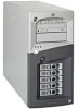
Controls and Indicators Table 1-4. Hot Swap Hard Drive LED Indicators Status LED · Off: Normal or unit not powered · Green (solid): - Normal and under power · - I/O activity · Amber (flashing): predictive failure · Amber (solid): hard drive failure Activity Status LED · Off: Normal · Green (flashing): I/O activity · Green (solid for more than one minute): Disk spinning up or "hung" Rear Panel The ports and connectors at the rear are listed below and shown in Figure 1-4. · The power connector accepts a standard power cable to connect the HP Server with a UPS or the site power source. · The mouse port accepts a standard mouse with a PS/2 connector. · The keyboard port accepts a standard keyboard with a PS/2 connector. · Two USB ports are provided for printers, scanners, and external modems. · The LAN port is an embedded controller based on Intel's 82550 10/100 BaseT Fast Ethernet controller. It has an RJ-45 LAN connector and two LEDs to indicate LAN speed and valid connection or activity. Table 1-5 describes the LED indicators. · The Serial Port A is a standard serial port. · The Parallel Port is a standard parallel port, which supports Extended Capabilities Port (ECP)/Enhanced Parallel Port (EPP). · The Serial Port B is a standard serial port. · The external SCSI port provides access to external SCSI devices, typically an external SCSI tape backup device. Figure 1-4. Rear Panel and Ports 4
-
 1
1 -
2
-
3
-
4
-
 5
5 -
 6
6 -
 7
7 -
 8
8 -
 9
9 -
 10
10 -
 11
11 -
 12
12 -
 13
13 -
 14
14 -
 15
15 -
16
-
17
-
18
-
19
-
20
-
21
-
22
-
23
-
24
-
25
-
26
-
27
-
28
-
29
-
30
-
31
-
32
-
33
-
34
-
35
-
36
-
37
-
38
-
39
-
40
-
41
-
42
-
43
-
44
-
45
-
46
-
47
-
48
-
49
-
50
-
51
-
52
-
53
-
54
-
55
-
56
-
57
-
58
-
59
-
60
-
61
-
62
-
63
-
64
-
65
-
66
-
67
-
68
-
69
-
70
-
71
-
72
-
73
-
74
-
75
-
76
-
77
-
78
-
79
-
80
-
81
-
82
-
83
-
84
-
85
-
86
-
87
-
88
-
89
-
90
-
91
-
92
-
93
-
94
-
95
-
96
-
97
-
98
-
99
-
100
-
101
-
102
-
103
-
104
-
105
-
106
-
107
-
108
-
109
-
110
-
111
 |
 |
