HP Server tc3100 hp server tc3100 operation and maintenance guide (English, v1 - Page 35
Removing the Terminator, Installing Processor
 |
View all HP Server tc3100 manuals
Add to My Manuals
Save this manual to your list of manuals |
Page 35 highlights
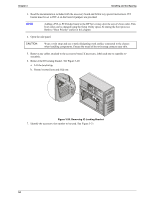
Chapter 3 Installing and Configuring Figure 3-17. Removing the Terminator 8. Lift the terminator out of the socket and place it on an anti-static surface or in a container. NOTE Keep the terminator for future use. The terminator must be installed in the secondary processor socket when only one processor is used or the HP Server will not operate properly. 9. Align the second processor over the empty processor socket. See Figure 3-18. CAUTION Ensure you align pin-1 of the processor with pin-1 of the processor socket or pin damage will occur. 10. Insert the second processor into the socket and close the ZIF lever to fully seat the processor. You should hear the ZIF lever click when it closes properly. Figure 3-18. Installing Processor 29
-
 1
1 -
2
-
3
-
4
-
5
-
6
-
7
-
8
-
9
-
10
-
11
-
12
-
13
-
14
-
15
-
16
-
17
-
18
-
19
-
20
-
21
-
22
-
23
-
24
-
25
-
26
-
27
-
28
-
29
-
 30
30 -
 31
31 -
 32
32 -
 33
33 -
 34
34 -
 35
35 -
 36
36 -
 37
37 -
 38
38 -
 39
39 -
 40
40 -
41
-
42
-
43
-
44
-
45
-
46
-
47
-
48
-
49
-
50
-
51
-
52
-
53
-
54
-
55
-
56
-
57
-
58
-
59
-
60
-
61
-
62
-
63
-
64
-
65
-
66
-
67
-
68
-
69
-
70
-
71
-
72
-
73
-
74
-
75
-
76
-
77
-
78
-
79
-
80
-
81
-
82
-
83
-
84
-
85
-
86
-
87
-
88
-
89
-
90
-
91
-
92
-
93
-
94
-
95
-
96
-
97
-
98
-
99
-
100
-
101
-
102
-
103
-
104
-
105
-
106
-
107
-
108
-
109
-
110
-
111
 |
 |

Chapter 3
Installing and Configuring
29
Figure 3-17. Removing the Terminator
8.
Lift the terminator out of the socket and place it on an anti-static surface or in a container.
NOTE
Keep the terminator for future use. The terminator must be installed in the secondary
processor socket when only one processor is used or the HP Server will not operate
properly.
9.
Align the second processor over the empty processor socket. See Figure 3-18.
CAUTION
Ensure you align pin-1 of the processor with pin-1 of the processor socket or pin damage
will occur.
10.
Insert the second processor into the socket and close the ZIF lever to fully seat the processor.
You should hear the ZIF lever click when it closes properly.
Figure 3-18. Installing Processor