HP Server tc3100 hp server tc3100 operation and maintenance guide (English, v1 - Page 40
Removing IO Locking Bracket
 |
View all HP Server tc3100 manuals
Add to My Manuals
Save this manual to your list of manuals |
Page 40 highlights
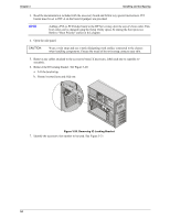
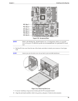
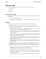
Chapter 3 Installing and Configuring 3. Read the documentation included with the accessory board and follow any special instructions. PCI boards must be set to INT A on the board if jumpers are provided. NOTE Adding a PCI-to-PCI bridge board to the HP Server may alter the server's boot order. This boot order can be changed using the Setup Utility (press F2 during the boot process). Refer to "Boot Priority" earlier in this chapter. 4. Open the side panel. CAUTION Wear a wrist strap and use a static-dissipating work surface connected to the chassis when handling components. Ensure the metal of the wrist strap contacts your skin. 5. Remove any cables attached to the accessory board. If necessary, label each one to expedite reassembly. 6. Remove the IO locking bracket. See Figure 3-20. a. Lift the bracket up. b. Rotate it toward you and slide out. Figure 3-20. Removing IO Locking Bracket 7. Identify the accessory slot number to be used. See Figure 3-21. 34
-
 1
1 -
2
-
3
-
4
-
5
-
6
-
7
-
8
-
9
-
10
-
11
-
12
-
13
-
14
-
15
-
16
-
17
-
18
-
19
-
20
-
21
-
22
-
23
-
24
-
25
-
26
-
27
-
28
-
29
-
30
-
31
-
32
-
33
-
34
-
 35
35 -
 36
36 -
 37
37 -
 38
38 -
 39
39 -
 40
40 -
 41
41 -
 42
42 -
 43
43 -
 44
44 -
 45
45 -
46
-
47
-
48
-
49
-
50
-
51
-
52
-
53
-
54
-
55
-
56
-
57
-
58
-
59
-
60
-
61
-
62
-
63
-
64
-
65
-
66
-
67
-
68
-
69
-
70
-
71
-
72
-
73
-
74
-
75
-
76
-
77
-
78
-
79
-
80
-
81
-
82
-
83
-
84
-
85
-
86
-
87
-
88
-
89
-
90
-
91
-
92
-
93
-
94
-
95
-
96
-
97
-
98
-
99
-
100
-
101
-
102
-
103
-
104
-
105
-
106
-
107
-
108
-
109
-
110
-
111
 |
 |
