HP Visualize b180L installing the hp Visualize workstation b132L/b160L to b180 - Page 24
Connecting the Storage Tray Cables
 |
View all HP Visualize b180L manuals
Add to My Manuals
Save this manual to your list of manuals |
Page 24 highlights
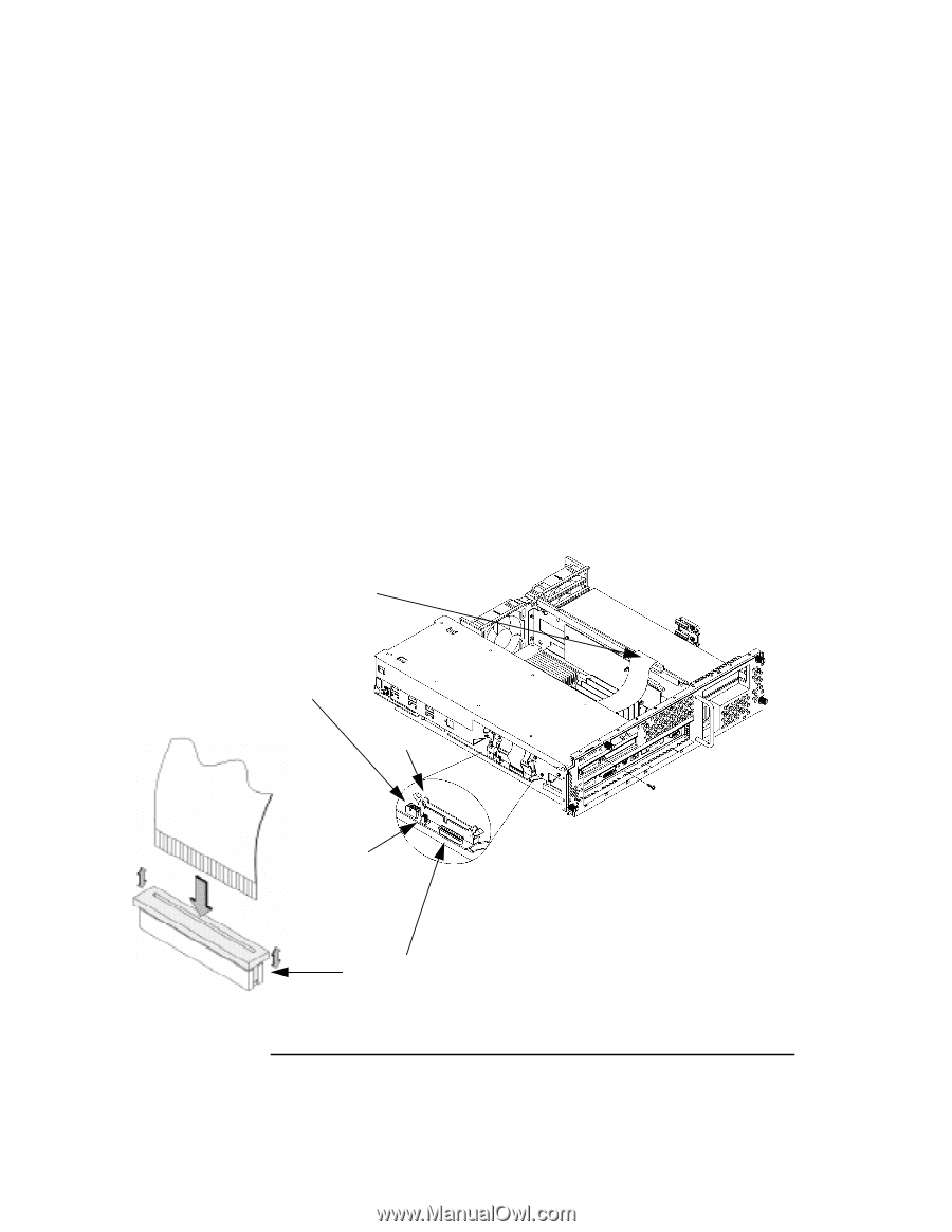
Replace the Storage Tray 5 Reconnect the floppy, SE SCSI, power, CD-ROM audio, and FW SCSI cables as shown in Figure 15. When connecting the floppy cable to the system board, use the following procedure: a Lift the locking ring on the connector to the up, or unlocked, position. b Hold the cable with the blue stripe on the inside, facing in the direction indicated in Figure 15 c While holding the locking ring in the unlocked position, insert the cable into the connector with the locking ring. d Press down on the locking ring evenly on both ends until it snaps into the down, or locked, position. 6 Reconnect any cables and/or terminators to the SCSI connectors on the rear of the chassis. FWSCSI Storage Tray Power SESCSI CD Audio Figure 15 Floppy Connector Connecting the Storage Tray Cables 22
-
 1
1 -
2
-
3
-
4
-
5
-
6
-
7
-
8
-
9
-
10
-
11
-
12
-
13
-
14
-
15
-
16
-
17
-
18
-
 19
19 -
 20
20 -
 21
21 -
 22
22 -
 23
23 -
 24
24 -
 25
25 -
 26
26 -
 27
27 -
 28
28
 |
 |