HP Visualize b180L installing the hp Visualize workstation b132L/b160L to b180 - Page 25
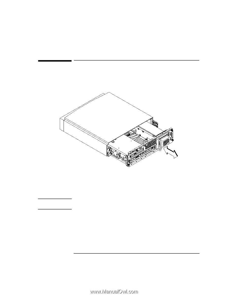
Replace the Main Tray Assembly
 |
View all HP Visualize b180L manuals
Add to My Manuals
Save this manual to your list of manuals |
Page 25 highlights
Replace the Main Tray Assembly Replace the Main Tray Assembly 1 Align the main tray assembly with the chassis and slide it into place, as shown in Figure 16. Figure 16 NOTICE: Replacing the Main Tray Assembly 2 Slide the main tray into the chassis until it is fully seated. 3 Tighten the four thumb screws. To maintain regulatory agency compliance, verify that the main tray is fully seated and all five thumb screws are completely tightened. 4 Replace the system unit in the floor stand. 5 Regardless of whether or not you have a supported graphics adapter, connect your monitor's 15-pin connector to the 15-pin connector on the EVC adapter cable which came with the upgrade kit. Connect the other end of the EVC adapter cable to the built-in video connector on the rear of the system. Be sure to tighten the thumbscrews on the connectors. 23
-
 1
1 -
2
-
3
-
4
-
5
-
6
-
7
-
8
-
9
-
10
-
11
-
12
-
13
-
14
-
15
-
16
-
17
-
18
-
19
-
 20
20 -
 21
21 -
 22
22 -
 23
23 -
 24
24 -
 25
25 -
 26
26 -
 27
27 -
 28
28
 |
 |