HP mt245 mt245 Mobile Thin Client Maintenance and Service Guide - Page 56
Display assembly
 |
View all HP mt245 manuals
Add to My Manuals
Save this manual to your list of manuals |
Page 56 highlights
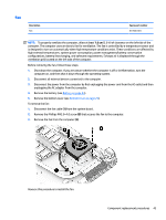
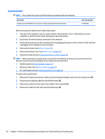
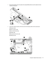
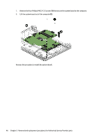
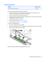
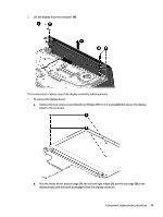
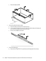
Display assembly This section describes removing the display assembly and disassembling display subcomponents. If you only need to remove the display bezel, webcam/microphone module, or display panel, you do not need to remove the entire display assembly from the computer. Description Raw display panel (35.6-cm [14.0-in], HD, WLED, BrightView; includes insulator screws) Antenna (includes insulator screws) Display bezel (includes insulator screws) Display cable (includes display panel cable and webcam/microphone cable; includes insulator screws) Display enclosure (includes insulator screws) Hinges (left and right) (includes insulator screws) Webcam/microphone module, VGA (includes insulator screws) Spare part number 814811-001 813485-001 815227-001 813503-001 814808-001 813511-001 813525-001 Before removing the display assembly, follow these steps: 1. Shut down the computer. If you are unsure whether the computer is off or in Hibernation, turn the computer on, and then shut it down through the operating system. 2. Disconnect all external devices connected to the computer. 3. Disconnect the power from the computer by first unplugging the power cord from the AC outlet and then unplugging the AC adapter from the computer. 4. Remove the battery (see Battery on page 24). 5. Remove the bottom cover (see Bottom cover on page 25). To remove the display assembly: 1. Remove the three Phillips PM2.5×5.0 screws (1), two Phillips broadhead PM2.0×2.0 screws (2) (on the right hinge), and one Phillips PM2.5×3.5 screw (3) (on the left hinge) that secures the display assembly to the computer. 48 Chapter 5 Removal and replacement procedures for Authorized Service Provider parts
-
 1
1 -
2
-
3
-
4
-
5
-
6
-
7
-
8
-
9
-
10
-
11
-
12
-
13
-
14
-
15
-
16
-
17
-
18
-
19
-
20
-
21
-
22
-
23
-
24
-
25
-
26
-
27
-
28
-
29
-
30
-
31
-
32
-
33
-
34
-
35
-
36
-
37
-
38
-
39
-
40
-
41
-
42
-
43
-
44
-
45
-
46
-
47
-
48
-
49
-
50
-
 51
51 -
 52
52 -
 53
53 -
 54
54 -
 55
55 -
 56
56 -
 57
57 -
 58
58 -
 59
59 -
 60
60 -
 61
61 -
62
-
63
-
64
-
65
-
66
-
67
-
68
-
69
-
70
-
71
-
72
-
73
-
74
-
75
-
76
-
77
-
78
-
79
-
80
-
81
-
82
-
83
-
84
-
85
-
86
-
87
-
88
-
89
-
90
-
91
-
92
-
93
-
94
-
95
-
96
-
97
-
98
 |
 |