HP mt245 mt245 Mobile Thin Client Maintenance and Service Guide - Page 57
bottom edge, Flex the inside of
 |
View all HP mt245 manuals
Add to My Manuals
Save this manual to your list of manuals |
Page 57 highlights
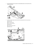
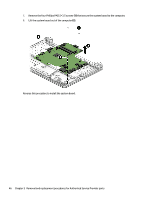
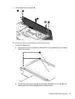
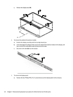
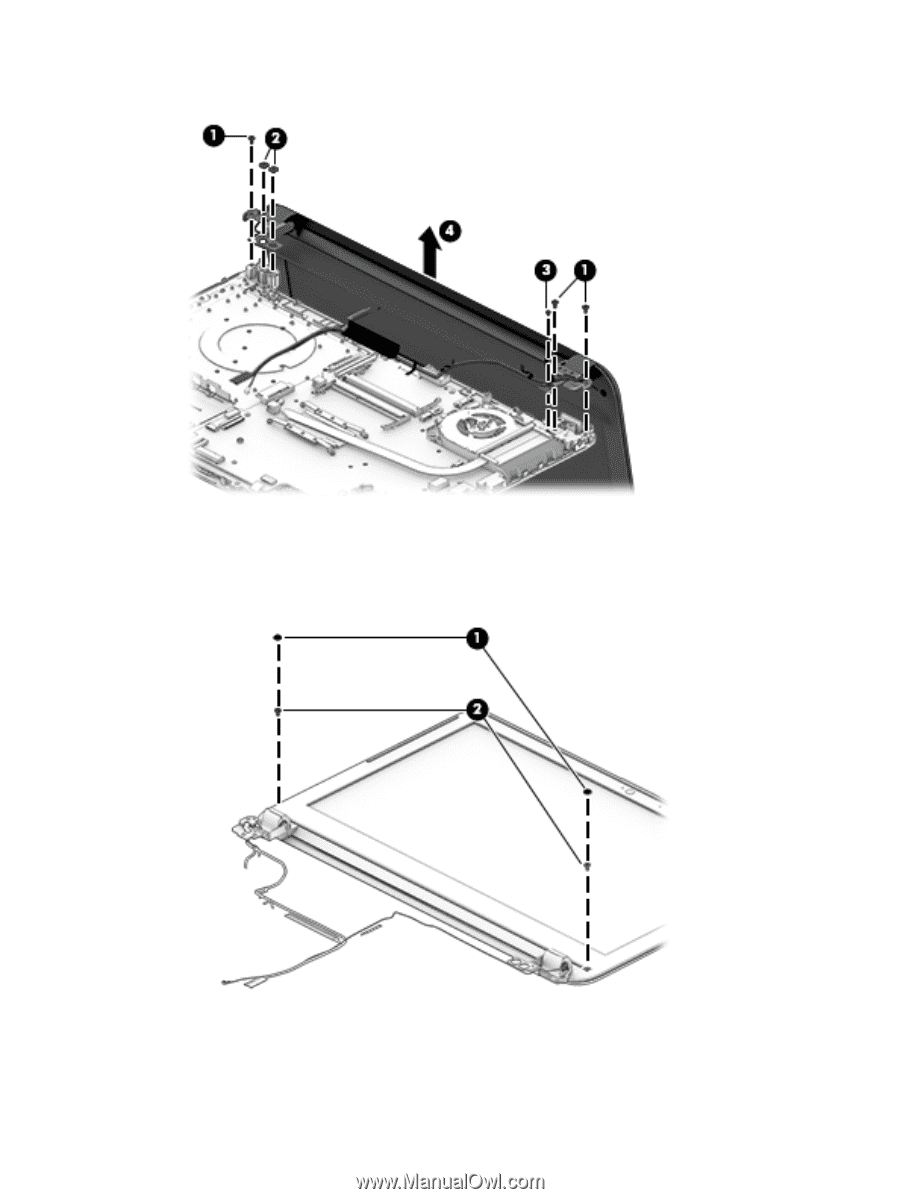
2. Lift the display from the computer (4). If it is necessary to replace any of the display assembly subcomponents: 1. To remove the display bezel: a. Remove the two screw covers (1) and two Phillips PM2.5×3.5 screws (2) that secure the display bezel to the enclosure. b. Flex the inside of the bottom edge (1), the left and right edges (2), and the top edge (3) of the display bezel until the bezel disengages from the display enclosure. Component replacement procedures 49
-
 1
1 -
2
-
3
-
4
-
5
-
6
-
7
-
8
-
9
-
10
-
11
-
12
-
13
-
14
-
15
-
16
-
17
-
18
-
19
-
20
-
21
-
22
-
23
-
24
-
25
-
26
-
27
-
28
-
29
-
30
-
31
-
32
-
33
-
34
-
35
-
36
-
37
-
38
-
39
-
40
-
41
-
42
-
43
-
44
-
45
-
46
-
47
-
48
-
49
-
50
-
51
-
 52
52 -
 53
53 -
 54
54 -
 55
55 -
 56
56 -
 57
57 -
 58
58 -
 59
59 -
 60
60 -
 61
61 -
 62
62 -
63
-
64
-
65
-
66
-
67
-
68
-
69
-
70
-
71
-
72
-
73
-
74
-
75
-
76
-
77
-
78
-
79
-
80
-
81
-
82
-
83
-
84
-
85
-
86
-
87
-
88
-
89
-
90
-
91
-
92
-
93
-
94
-
95
-
96
-
97
-
98
 |
 |
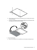
2.
Lift the display from the computer
(4)
.
If it is necessary to replace any of the display assembly subcomponents:
1.
To remove the display bezel:
a.
Remove the two screw covers
(1)
and two Phillips PM2.5×3.5 screws
(2)
that secure the display
bezel to the enclosure.
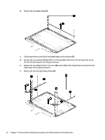
b.
Flex the inside of the
bottom edge
(1)
, the left and right edges
(2)
, and the top edge
(3)
of the
display bezel until the bezel disengages from the display enclosure.
Component replacement procedures
49