HP mt245 mt245 Mobile Thin Client Maintenance and Service Guide - Page 74
Power-On Sequence, Power-On Diagnostic Tests, Troubleshooting
 |
View all HP mt245 manuals
Add to My Manuals
Save this manual to your list of manuals |
Page 74 highlights
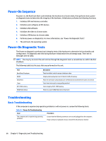
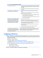
Power-On Sequence At power-on, the flash boot block code initializes the hardware to a known state, then performs basic poweron diagnostic tests to determine the integrity of the hardware. Initialization performs the following functions: 1. Initializes CPU and memory controller. 2. Initializes and configures all PCI devices. 3. Initializes VGA software. 4. Initializes the video to a known state. 5. Initializes USB devices to a known state. 6. Performs power-on diagnostics. For more information, see "Power-On Diagnostic Tests". 7. The unit boots the operating system. Power-On Diagnostic Tests The Power-on diagnostics performs basic integrity tests of the hardware to determine its functionality and configuration. If a diagnostic test fails during hardware initialization the unit simply stops. There are no messages sent to video. NOTE: You may try to restart the unit and run through the diagnostic tests a second time to confirm the first shutdown. The following table lists the tests that are performed on the unit. Test Boot Block Checksum DRAM Serial Port Timer RTC CMOS battery NAND flash device Description Tests boot block code for proper checksum value Simple write/read pattern test of the first 640k of memory Tests the serial port using simple port verification test to determine if ports are present Tests timer interrupt by using polling method Tests integrity of RTC CMOS battery Tests for proper NAND flash device ID present Troubleshooting Basic Troubleshooting If the computer is experiencing operating problems or will not power on, review the following items. Table 8-1 Power-On Troubleshooting Issue Procedures The computer unit is experiencing operating problems. Ensure that the following connectors are securely plugged into the computer: Power connector, keyboard, mouse, network RJ-45 connector, monitor 66 Chapter 8 Diagnostics and Troubleshooting
-
 1
1 -
2
-
3
-
4
-
5
-
6
-
7
-
8
-
9
-
10
-
11
-
12
-
13
-
14
-
15
-
16
-
17
-
18
-
19
-
20
-
21
-
22
-
23
-
24
-
25
-
26
-
27
-
28
-
29
-
30
-
31
-
32
-
33
-
34
-
35
-
36
-
37
-
38
-
39
-
40
-
41
-
42
-
43
-
44
-
45
-
46
-
47
-
48
-
49
-
50
-
51
-
52
-
53
-
54
-
55
-
56
-
57
-
58
-
59
-
60
-
61
-
62
-
63
-
64
-
65
-
66
-
67
-
68
-
 69
69 -
 70
70 -
 71
71 -
 72
72 -
 73
73 -
 74
74 -
 75
75 -
 76
76 -
 77
77 -
 78
78 -
 79
79 -
80
-
81
-
82
-
83
-
84
-
85
-
86
-
87
-
88
-
89
-
90
-
91
-
92
-
93
-
94
-
95
-
96
-
97
-
98
 |
 |