IBM 72332MU Installation Guide - Page 41
Connecting the cables, Updating the server configuration, Rear view, Front view
 |
UPC - 883436084673
View all IBM 72332MU manuals
Add to My Manuals
Save this manual to your list of manuals |
Page 41 highlights
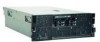
5. Update the server configuration. See "Updating the server configuration" for more information. Connecting the cables See the documentation that comes with optional devices for additional cabling instructions. It might be easier for you to route cables before you install certain optional devices. Cable identifiers are printed on the cables that come with the server and optional devices. Use these identifiers to connect the cables to the correct connectors. For details about the locations and functions of the input and output connectors, see Chapter 3, "Server controls, connectors, LEDs, and power," on page 37. When available, you can install one or more optional SMP Expansion kits to interconnect the SMP Expansion ports of two or more servers. The following illustrations show the locations of the input and output connectors on the server. Detailed cabling instructions are in the Rack Installation Instructions that come with the server. Rear view SAS USB System serial Remote Supervisor Adapter II Power-supply 1 Front view SMP expansion port 1 SMP expansion port 2 SMP expansion port 3 Power-control button/power-on LED Ethernet icon LED 1 2 Power-supply 2 Gigabit Ethernet 1 Gigabit Ethernet 2 Information LED System-error LED Power-control button cover Ethernet port activity LEDs Locator button/locator LED Updating the server configuration When you start the server for the first time after you add or remove an internal optional device or external SAS or SCSI device, you might receive a message that Chapter 2. Installing optional devices 29
-
 1
1 -
2
-
3
-
4
-
5
-
6
-
7
-
8
-
9
-
10
-
11
-
12
-
13
-
14
-
15
-
16
-
17
-
18
-
19
-
20
-
21
-
22
-
23
-
24
-
25
-
26
-
27
-
28
-
29
-
30
-
31
-
32
-
33
-
34
-
35
-
 36
36 -
 37
37 -
 38
38 -
 39
39 -
 40
40 -
 41
41 -
 42
42 -
 43
43 -
 44
44 -
 45
45 -
 46
46 -
47
-
48
-
49
-
50
-
51
-
52
-
53
-
54
-
55
-
56
-
57
-
58
-
59
-
60
-
61
-
62
-
63
-
64
-
65
-
66
-
67
-
68
-
69
-
70
-
71
-
72
-
73
-
74
-
75
-
76
-
77
-
78
-
79
-
80
-
81
-
82
-
83
-
84
-
85
-
86
-
87
-
88
-
89
-
90
-
91
-
92
-
93
-
94
-
95
-
96
-
97
-
98
-
99
-
100
-
101
-
102
 |
 |
