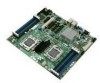
Intel S5500BC User Guide - Page 13

List of s - memory configuration

Page 13 highlights

List of Figures Figure 1. Intel® Server Board S5500BC 1 Figure 2. Server Board Connector and Component Locations 3 Figure 3. Configuration Jumper Locations 5 Figure 4. Back Panel Connectors 7 Figure 5. DIMM Configuration Diagram 10 Figure 6. Channel Slots Configuration 11 Figure 7. Installing Memory ...14 Figure 8. Lifting the Load Lever 15 Figure 9. Open the Load Plate 16 Figure 10. Remove the Socket Protective Cover 16 Figure 11. Remove the Processor Protective Cover 16 Figure 12. Installing the Processor 17 Figure 13. Close the Load Plate and Socket Lever 17 Figure 14. 2U Reference Heat Sink Assembly 18 Figure 15. Removing the PCI Riser Assembly from the Server System 20 Figure 16. Installing a PCI Card in a Riser Card 21 Figure 17. Replacing the Backup Battery 23 Figure 18. BIOS Recovery Jumper 29 Figure 19. Password Recovery Jumper 30 Figure 20. CMOS Recovery Jumper 31 Figure 21. Diagnostic LED Placement Diagram 51 Intel® Server Board S5500BC User's Guide xiii

  • 1
  • 2
  • 3
  • 4
  • 5
  • 6
  • 7
  • 8
  • 9
  • 10
  • 11
  • 12
  • 13
  • 14
  • 15
  • 16
  • 17
  • 18
  • 19
  • 20
  • 21
  • 22
  • 23
  • 24
  • 25
  • 26
  • 27
  • 28
  • 29
  • 30
  • 31
  • 32
  • 33
  • 34
  • 35
  • 36
  • 37
  • 38
  • 39
  • 40
  • 41
  • 42
  • 43
  • 44
  • 45
  • 46
  • 47
  • 48
  • 49
  • 50
  • 51
  • 52
  • 53
  • 54
  • 55
  • 56
  • 57
  • 58
  • 59
  • 60
  • 61
  • 62
  • 63
  • 64
  • 65
  • 66
  • 67
  • 68
  • 69
  • 70
  • 71
  • 72
  • 73
  • 74
  • 75
  • 76
  • 77
  • 78
  • 79
  • 80
  • 81
  • 82
  • 83
  • 84
  • 85
  • 86

Intel
®
Server Board S5500BC User’s Guide
xiii
List of Figures
Figure 1. Intel
®
Server Board S5500BC
.....................................................................................
1
Figure 2. Server Board Connector and Component Locations
..................................................
3
Figure 3. Configuration Jumper Locations
.................................................................................
5
Figure 4. Back Panel Connectors
...............................................................................................
7
Figure 5. DIMM Configuration Diagram
....................................................................................
10
Figure 6. Channel Slots Configuration
.....................................................................................
11
Figure 7. Installing Memory
......................................................................................................
14
Figure 8. Lifting the Load Lever
................................................................................................
15
Figure 9. Open the Load Plate
.................................................................................................
16
Figure 10. Remove the Socket Protective Cover
.....................................................................
16
Figure 11. Remove the Processor Protective Cover
................................................................
16
Figure 12. Installing the Processor
...........................................................................................
17
Figure 13. Close the Load Plate and Socket Lever
..................................................................
17
Figure 14. 2U Reference Heat Sink Assembly
.........................................................................
18
Figure 15. Removing the PCI Riser Assembly from the Server System
..................................
20
Figure 16. Installing a PCI Card in a Riser Card
......................................................................
21
Figure 17. Replacing the Backup Battery
.................................................................................
23
Figure 18. BIOS Recovery Jumper
..........................................................................................
29
Figure 19. Password Recovery Jumper
...................................................................................
30
Figure 20. CMOS Recovery Jumper
........................................................................................
31
Figure 21. Diagnostic LED Placement Diagram
.......................................................................
51