Intel S5500BC User Guide - Page 23
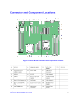
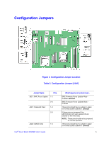
Connector and Component Locations
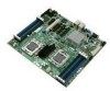 |
UPC - 735858208109
View all Intel S5500BC manuals
Add to My Manuals
Save this manual to your list of manuals |
Page 23 highlights
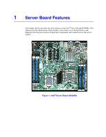
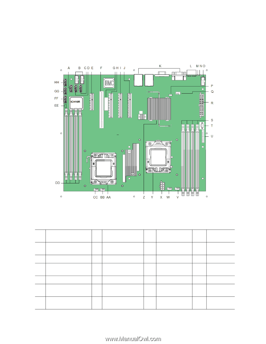
Connector and Component Locations Figure 2. Server Board Connector and Component Locations A. SATA 3 L. Diagnostic LEDs W. CPU 1 fan header B. Internal dual port USB2.0 header M. Status LED X. CPU Power Connector C. SATA 5 D. SATA 4 N. ID LED O. External Serial B header Y. CPU Socket 1 Z. Intel® IOH 5500 chipset E. Slot 3, PCI Express* x4 P. SATA Key AA. CPU Socket 2 F. Slot 4, 32-bit/33 MHz PCI G. Intel® RMM3 slot Q. System fan 3 header BB. BB CPU 2 Fan header R. Main power connector CC. System Fan 1 header HH. SATA 2 Intel® Server Board S5500BC User's Guide 3
-
 1
1 -
2
-
3
-
4
-
5
-
6
-
7
-
8
-
9
-
10
-
11
-
12
-
13
-
14
-
15
-
16
-
17
-
 18
18 -
 19
19 -
 20
20 -
 21
21 -
 22
22 -
 23
23 -
 24
24 -
 25
25 -
 26
26 -
 27
27 -
 28
28 -
29
-
30
-
31
-
32
-
33
-
34
-
35
-
36
-
37
-
38
-
39
-
40
-
41
-
42
-
43
-
44
-
45
-
46
-
47
-
48
-
49
-
50
-
51
-
52
-
53
-
54
-
55
-
56
-
57
-
58
-
59
-
60
-
61
-
62
-
63
-
64
-
65
-
66
-
67
-
68
-
69
-
70
-
71
-
72
-
73
-
74
-
75
-
76
-
77
-
78
-
79
-
80
-
81
-
82
-
83
-
84
-
85
-
86
 |
 |
Intel
®
Server Board S5500BC User’s Guide
3
Connector and Component Locations
Figure 2. Server Board Connector and Component Locations
A.
SATA 3
L.
Diagnostic LEDs
W.
CPU 1 fan
header
HH.
SATA 2
B.
Internal dual port
USB2.0 header
M.
Status LED
X.
CPU Power
Connector
C.
SATA 5
N.
ID LED
Y.
CPU Socket 1
D.
SATA 4
O.
External Serial B
header
Z.
Intel
®
IOH 5500
chipset
E.
Slot 3, PCI Express* x4
P.
SATA Key
AA.
CPU Socket 2
F.
Slot 4, 32-bit/33 MHz
PCI
Q.
System fan 3 header
BB.
BB CPU 2 Fan
header
G.
Intel
®
RMM3 slot
R.
Main power
connector
CC.
System Fan 1
header