Intel S5500BC User Guide - Page 37
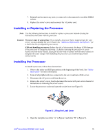
Installing the Retention Mechanisms and Heat Sinks
 |
UPC - 735858208109
View all Intel S5500BC manuals
Add to My Manuals
Save this manual to your list of manuals |
Page 37 highlights
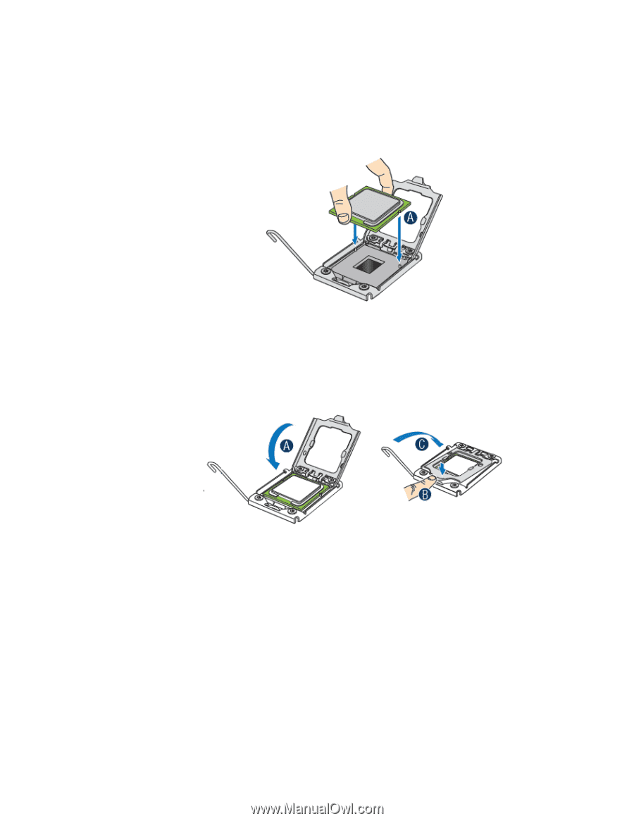
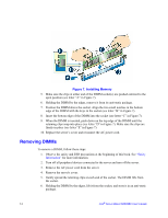
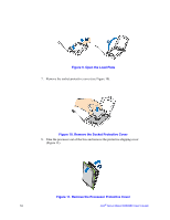
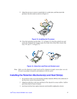
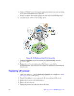
9. Align the processor cutouts to match the two socket pins, and then insert the processor into the socket as shown in Figure 12. Figure 12. Installing the Processor 10. Close the load plate (see the letter "A" in Figure 13), close the socket lever and ensure the load plate tab engages under the socket lever when fully closed. (See letter "B" and "C" in Figure 13) Figure 13. Close the Load Plate and Socket Lever Note: Make sure the alignment triangle mark and the alignment triangle cutout align correctly. To assist in package orientation and alignment with the socket: Installing the Retention Mechanism(s) and Heat Sink(s) 1. If a protective film covers the thermal interface material (TIM) on the underside of the heat sink, remove the protective film. 2. Align heat sink fins to the front and back of the chassis for correct airflow. Airflow goes from front-to-back of chassis. 3. Each heat sink has four captive fasteners and should be tightened as shown. Intel® Server Board S5500BC User's Guide 17
-
 1
1 -
2
-
3
-
4
-
5
-
6
-
7
-
8
-
9
-
10
-
11
-
12
-
13
-
14
-
15
-
16
-
17
-
18
-
19
-
20
-
21
-
22
-
23
-
24
-
25
-
26
-
27
-
28
-
29
-
30
-
31
-
 32
32 -
 33
33 -
 34
34 -
 35
35 -
 36
36 -
 37
37 -
 38
38 -
 39
39 -
 40
40 -
 41
41 -
 42
42 -
43
-
44
-
45
-
46
-
47
-
48
-
49
-
50
-
51
-
52
-
53
-
54
-
55
-
56
-
57
-
58
-
59
-
60
-
61
-
62
-
63
-
64
-
65
-
66
-
67
-
68
-
69
-
70
-
71
-
72
-
73
-
74
-
75
-
76
-
77
-
78
-
79
-
80
-
81
-
82
-
83
-
84
-
85
-
86
 |
 |