Intel S5500BC User Guide - Page 71
Appendix B, LED Decoder
 |
UPC - 735858208109
View all Intel S5500BC manuals
Add to My Manuals
Save this manual to your list of manuals |
Page 71 highlights
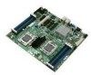
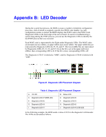
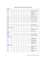
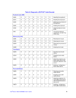
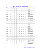
Appendix B: LED Decoder During the system boot process, the BIOS executes a number of platform configuration processes, each of which is assigned a specific hex POST code number. As each configuration routine is started, the BIOS displays the POST code to the POST Code Diagnostic LEDs on the back edge of the server board. To assist in troubleshooting a system hang during the POST process, you can use the Diagnostic LEDs to identify the last POST process that was executed. Each POST code is represented by the Eight amber Diagnostic LEDs. The POST codes are divided into two nibbles, an upper nibble and a lower nibble. The upper nibble bits are represented by Diagnostic LEDs #4, #5, #6, and #7. The lower nibble bits are represented by Diagnostics LEDs #0, #1, #2, and #3. Given the bit is set in the upper and lower nibbles, then corresponding LED is lit. If the bit is clear, corresponding LED is off. The Diagnostic LED #7 is labeled as "MSB", and the Diagnostic LED #0 is labeled with "LSB". Figure 21. Diagnostic LED Placement Diagram Table 6. Diagnostic LED Placement Diagram A. ID LED C. Diagnostic LED #7 (MSB LED) E. Diagnostic LED #5 G. Diagnostic LED #3 I. Diagnostic LED #1 B. Status LED D. Diagnostic LED #6 F. Diagnostic LED #4 H. Diagnostic LED #2 J. Diagnostic LED #0 (LSB LED) In the following example, the BIOS sends a value of ACh to the diagnostic LED decoder. The LEDs are decoded as follows.
-
 1
1 -
2
-
3
-
4
-
5
-
6
-
7
-
8
-
9
-
10
-
11
-
12
-
13
-
14
-
15
-
16
-
17
-
18
-
19
-
20
-
21
-
22
-
23
-
24
-
25
-
26
-
27
-
28
-
29
-
30
-
31
-
32
-
33
-
34
-
35
-
36
-
37
-
38
-
39
-
40
-
41
-
42
-
43
-
44
-
45
-
46
-
47
-
48
-
49
-
50
-
51
-
52
-
53
-
54
-
55
-
56
-
57
-
58
-
59
-
60
-
61
-
62
-
63
-
64
-
65
-
 66
66 -
 67
67 -
 68
68 -
 69
69 -
 70
70 -
 71
71 -
 72
72 -
 73
73 -
 74
74 -
 75
75 -
 76
76 -
77
-
78
-
79
-
80
-
81
-
82
-
83
-
84
-
85
-
86
 |
 |
