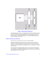
Intel S5500BC User Guide - Page 33
Hardware Installations and, Upgrades - manual
 |
UPC - 735858208109
View all Intel S5500BC manuals
Add to My Manuals
Save this manual to your list of manuals |
Page 33 highlights
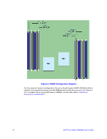
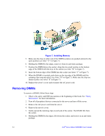
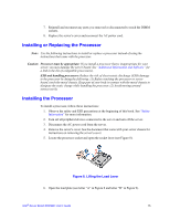
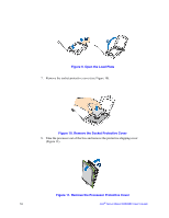
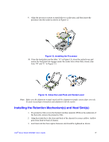
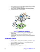
2 Hardware Installations and Upgrades Before You Begin Before working with your server product, pay close attention to the "Safety Information" at the beginning of this manual. Tools and Supplies Needed • Phillips* (cross head) screwdrivers (#1 bit and #2 bit) • Needle nosed pliers • A ruler • Pen or pencil • Antistatic wrist strap and conductive foam pad (recommended) Installing and Removing Memory The silkscreen on the board for the DIMMs displays DIMM_A1, DIMM_A2, DIMM_B1, and DIMM_B2, DIMM_D1, DIMM_D2, DIMM_E1, DIMM_E2 starting from the inside of the board. DIMM_A1 is the socket in blue closest to the processor 1 socket. For two slots per channel configurations, the server board requires DDR3 DIMMs within a channel to be populated starting with the DIMM farthest from the processor. The DIMM farthest from the processor per channel is blue on the board. Installing DIMMs To install DIMMs, follow these steps: 1. Observe the safety and ESD precautions at the beginning of this book. See "Safety Information" for more information. 2. Turn off all peripheral devices connected to the server and turn off the server. 3. Disconnect the AC power cord from the server. 4. Remove the server's cover and locate the DIMM sockets (see letter "A" to "E" in Figure 7).
-
 1
1 -
2
-
3
-
4
-
5
-
6
-
7
-
8
-
9
-
10
-
11
-
12
-
13
-
14
-
15
-
16
-
17
-
18
-
19
-
20
-
21
-
22
-
23
-
24
-
25
-
26
-
27
-
 28
28 -
 29
29 -
 30
30 -
 31
31 -
 32
32 -
 33
33 -
 34
34 -
 35
35 -
 36
36 -
 37
37 -
 38
38 -
39
-
40
-
41
-
42
-
43
-
44
-
45
-
46
-
47
-
48
-
49
-
50
-
51
-
52
-
53
-
54
-
55
-
56
-
57
-
58
-
59
-
60
-
61
-
62
-
63
-
64
-
65
-
66
-
67
-
68
-
69
-
70
-
71
-
72
-
73
-
74
-
75
-
76
-
77
-
78
-
79
-
80
-
81
-
82
-
83
-
84
-
85
-
86
 |
 |