Intel SE7505VB2 Product Specification - Page 19
Memory Configuration, Memory Cooling, DIMM capacity: 128 MB, 256 MB, 512 MB, 1 GB, 2GB DIMMs - specification
 |
View all Intel SE7505VB2 manuals
Add to My Manuals
Save this manual to your list of manuals |
Page 19 highlights
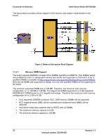
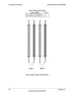
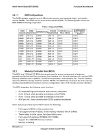
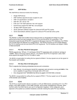
Intel® Server Board SE7505VB2 Functional Architecture 3.1.2.2 Memory Configuration The memory interface between the MCH and the DIMMs is 144-bits wide (72-bits for each bank). There are two banks of DIMMs, labeled 1 and 2. Bank 1 contains DIMM socket locations 1A and 1B. Bank 2 contains 2A and 2B. The sockets associated with each bank are located next to each other and the DIMM socket identifiers are marked on the baseboard silkscreen, near the DIMM socket. For designs that require a lower price point, a single 128 MB DIMM can be populated in the DIMM1A socket. When a single DIMM is installed, interleaving and Intel x4 SDDC are not available. Bank 2 will only operate with two DIMMs installed. The baseboard's signal integrity and cooling are optimized when memory banks are populated in order. Before populating either DIMM socket in bank 2, both DIMMs in bank 1 must be populated. No empty DIMM sockets are allowed between populated DIMMs. DIMM and memory configurations must adhere to the following: DDR266 ECC, registered, DDR DIMM modules DIMM organization: x72 ECC Pin count: 184 DIMM capacity: 128 MB, 256 MB, 512 MB, 1 GB, 2GB DIMMs Serial PD: JEDEC Rev 2.0 Voltage options: 3.3 V (VDD/VDDQ) Interface: SSTL2 3.1.2.3 Memory Cooling The SE7505VB2 server board supports DDR memory in a variety of sizes and densities (see Table 4). Due to the specific orientation of the memory on the SE7505VB2 server board, certain memory densities and configurations are more difficult to cool in chassis that provide traditional front to back airflow such as the Intel SC5200 and SC5250-E server chassis. To ensure the memory used with this board has sufficient thermal margin to operate within specifications, Intel has designed a memory cooling duct specifically for the SE7505VB2 server board. Intel's testing has shown only 2GB and stacked 1GB (low profile) DIMMs are thermally at risk. If your specific design uses either of these size memory parts, contact Intel Customer Support and request the SE7505VB2 server board memory cooling duct, part number C28482001. Revision 1.2 19 Intel part number C32194-002
-
 1
1 -
2
-
3
-
4
-
5
-
6
-
7
-
8
-
9
-
10
-
11
-
12
-
13
-
 14
14 -
 15
15 -
 16
16 -
 17
17 -
 18
18 -
 19
19 -
 20
20 -
 21
21 -
 22
22 -
 23
23 -
 24
24 -
25
-
26
-
27
-
28
-
29
-
30
-
31
-
32
-
33
-
34
-
35
-
36
-
37
-
38
-
39
-
40
-
41
-
42
-
43
-
44
-
45
-
46
-
47
-
48
-
49
-
50
-
51
-
52
-
53
-
54
-
55
-
56
-
57
-
58
-
59
-
60
-
61
-
62
-
63
-
64
-
65
-
66
-
67
-
68
-
69
-
70
-
71
-
72
-
73
-
74
-
75
-
76
-
77
-
78
-
79
-
80
-
81
-
82
-
83
-
84
-
85
-
86
-
87
-
88
-
89
-
90
-
91
-
92
-
93
-
94
-
95
-
96
-
97
-
98
-
99
-
100
-
101
-
102
-
103
-
104
-
105
-
106
-
107
-
108
 |
 |