Intel SE7505VB2 Product Specification - Page 40
Interrupt Routing
 |
View all Intel SE7505VB2 manuals
Add to My Manuals
Save this manual to your list of manuals |
Page 40 highlights
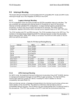
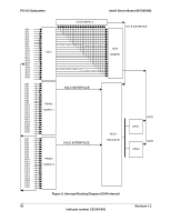
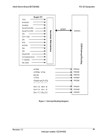
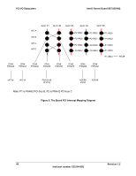
PCI I/O Subsystem Intel® Server Board SE7505VB2 5.5 Interrupt Routing The board interrupt architecture accommodates both PC-compatible PIC mode and APIC mode interrupts through use of the integrated I/O APICs in the ICH4. 5.5.1 Legacy Interrupt Routing For PC-compatible mode, the ICH4 provides two 82C59-compatible interrupt controllers. The two controllers are cascaded with interrupt levels 8-15 entering on level 2 of the primary interrupt controller (standard PC configuration). A single interrupt signal is presented to the processors, to which only one processor will respond for servicing. The ICH4 contains configuration registers that define which interrupt source logically maps to I/O APIC INTx pins. The ICH4 handles both PCI and IRQ interrupts. The ICH4 translates these to the APIC bus. The numbers in the table below indicate the ICH4 PCI interrupt input pin to which the associated device interrupt (INTA, INTB, INTC, INTD) is connected. The ICH4 I/O APIC exists on the I/O APIC bus with the processors. AGPA# Interrupt AGPB# VGA# sATA# NIC1# NIC2# P64H2-A# [P1/P2] P64-C Slot 5 P64-B Slot 4 P64-B Slot 3 P32-A Slot 2 P32-A Slot 1 Table 16. PCI Interrupt Routing/Sharing INT A ICH4_PIRQA# ICH4_PIRQB# ICH4_PIRQB# ICH4_PIRQD# ICH4-PIRQC# P1-IRQ4# ICH4_PIRQE# P1_IRQ0# P2_IRQ0# P2_IRQ4# ICH4_PIRQG# ICH4_PIRQF# INT B P1_IRQ1# P2_IRQ1# P2_IRQ5# ICH4_PIRQF# ICH4_PIRQG# INT C P1_IRQ2# P2_IRQ2# P2_IRQ6# ICH4_PIRQE# ICH4_PIRQH# INT D P1_IRQ3# P2_IRQ3# P2_IRQ7# ICH4_PIRQH# ICH4_PIRQE# 5.5.2 APIC Interrupt Routing For APIC mode, the baseboard interrupt architecture incorporates three Intel® I/O APIC devices to manage and broadcast interrupts to local APICs in each processor. The Intel I/O APICs monitor each interrupt on each PCI device, including PCI slots in addition to the ISA compatibility interrupts IRQ(0-15). When an interrupt occurs, a message corresponding to the interrupt is sent across a three-wire serial interface to the local APICs. The APIC bus minimizes interrupt latency time for compatibility interrupt sources. The I/O APICs can also supply greater than 16 interrupt levels to the processor(s). This APIC bus consists of an APIC clock and two bidirectional data lines. 40 Revision 1.2 Intel part number C32194-002
-
 1
1 -
2
-
3
-
4
-
5
-
6
-
7
-
8
-
9
-
10
-
11
-
12
-
13
-
14
-
15
-
16
-
17
-
18
-
19
-
20
-
21
-
22
-
23
-
24
-
25
-
26
-
27
-
28
-
29
-
30
-
31
-
32
-
33
-
34
-
 35
35 -
 36
36 -
 37
37 -
 38
38 -
 39
39 -
 40
40 -
 41
41 -
 42
42 -
 43
43 -
 44
44 -
 45
45 -
46
-
47
-
48
-
49
-
50
-
51
-
52
-
53
-
54
-
55
-
56
-
57
-
58
-
59
-
60
-
61
-
62
-
63
-
64
-
65
-
66
-
67
-
68
-
69
-
70
-
71
-
72
-
73
-
74
-
75
-
76
-
77
-
78
-
79
-
80
-
81
-
82
-
83
-
84
-
85
-
86
-
87
-
88
-
89
-
90
-
91
-
92
-
93
-
94
-
95
-
96
-
97
-
98
-
99
-
100
-
101
-
102
-
103
-
104
-
105
-
106
-
107
-
108
 |
 |