Intel SE7505VB2 Product Specification - Page 36
Video Controller, PCI I/O Subsystem, Intel® Server Board SE7505VB2, Table 14. sATA RAID Level - server board drivers
 |
View all Intel SE7505VB2 manuals
Add to My Manuals
Save this manual to your list of manuals |
Page 36 highlights
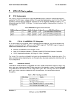
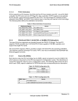
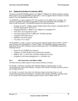
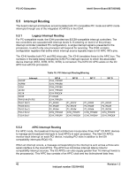
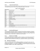
PCI I/O Subsystem Intel® Server Board SE7505VB2 The baseboard ships with the Silicon Image controller set to Base ATA mode. To switch the controller to RAID mode, a utility needs to be downloaded from the SE7505VB2 support website or run from the resource CD. This utility switches the controller from one mode to the other. Appropriate drivers need to be loaded, depending on the mode the controller is set to. This method was chosen over a BIOS F2 setup switch to allow the controller settings to be maintained in the event of a Clear CMOS operation. If the RAID drivers were loaded and a Clear CMOS operation was executed, but the device was not reset to RAID mode, the operating system would not load. Refer to the SE7505VB2 support website for details on which operating systems support RAID mode. Note: The onboard NICs need to be enabled for the ATA mode/RAID mode utility to properly program the device. The utility toggles the Sub-System ID (SSID) in the NIC EEPROM between two different values. The BIOS will load the appropriate Silicon Image Option ROM based on the SSID that is set in the NIC EEPROM. The NICs need to be enabled for the BIOS to know which SSID is set and subsequently which option ROM to load. When in RAID mode, the Silicon Image controller can support the following RAID levels: RAID Level Table 14. sATA RAID Level Performance Capacity RAID 0 (Striping) Highest RAID 1 (Mirroring) Normal Number of drives multiplied by the smallest drive size 50% min # of Drives 2 2 RAID 0 configurations are primarily used for high performance applications, as it doubles the sustained transfer rate of its drives. RAID 1 configurations are primarily used for data protection. RAID 1 creates an identical backup of the primary drive to a secondary drive. Whenever a disk write is performed, the controller sends data simultaneously to a second drive located on a different data channel. 5.3 Video Controller The baseboard provides an ATI Rage XL PCI graphics accelerator, along with 8 MB of video SDRAM and support circuitry for an embedded SVGA video subsystem. The ATI Rage XL chip contains a SVGA video controller, clock generator, 2D and 3D engine, and RAMDAC in a 272pin PBGA. One 2Mx32 SDRAM chip provides 8 MB of video memory. The SVGA subsystem supports a variety of modes, up to 1600 x 1200 resolution in 8/16/24/32 bpp modes under 2D, and up to 1024 x 768 resolution in 8/16/24/32 bpp modes under 3D. It supports both CRT and LCD monitors with up to 100 Hz vertical refresh rate. The baseboard provides a standard 15-pin VGA connector at the rear of the system, in the standard ATX I/O opening area. The video controller disabled by default in BIOS Setup when an off-board video adapter is detected in either the AGP or PCI slots. Optionally, the video controller can be set to support dual monitor mode when an off-board AGP adapter is detected. The onboard controller would act as the primary video controller and the AGP adapter becomes the secondary adapter under an operating system that supports this functionality. 36 Revision 1.2 Intel part number C32194-002
-
 1
1 -
2
-
3
-
4
-
5
-
6
-
7
-
8
-
9
-
10
-
11
-
12
-
13
-
14
-
15
-
16
-
17
-
18
-
19
-
20
-
21
-
22
-
23
-
24
-
25
-
26
-
27
-
28
-
29
-
30
-
 31
31 -
 32
32 -
 33
33 -
 34
34 -
 35
35 -
 36
36 -
 37
37 -
 38
38 -
 39
39 -
 40
40 -
 41
41 -
42
-
43
-
44
-
45
-
46
-
47
-
48
-
49
-
50
-
51
-
52
-
53
-
54
-
55
-
56
-
57
-
58
-
59
-
60
-
61
-
62
-
63
-
64
-
65
-
66
-
67
-
68
-
69
-
70
-
71
-
72
-
73
-
74
-
75
-
76
-
77
-
78
-
79
-
80
-
81
-
82
-
83
-
84
-
85
-
86
-
87
-
88
-
89
-
90
-
91
-
92
-
93
-
94
-
95
-
96
-
97
-
98
-
99
-
100
-
101
-
102
-
103
-
104
-
105
-
106
-
107
-
108
 |
 |